
Arduino Guitar Pedal

The schematic serves as a visual representation of the circuit layout, detailing the connections between various electronic components. It is essential to follow the schematic closely to ensure proper functionality of the circuit. The components may include resistors, capacitors, diodes, transistors, and integrated circuits, each serving a specific role within the circuit.
To effectively build the circuit, gather all necessary components and tools, including a breadboard or PCB for assembly, soldering equipment if required, and a multimeter for testing. Begin by placing the components on the board according to the schematic, ensuring that all connections align correctly with the designated pins and terminals.
Once the components are in place, proceed with wiring. It is advisable to use color-coded wires for clarity, where red typically indicates positive connections and black denotes negative. After wiring is complete, double-check all connections against the schematic to prevent errors.
After assembly, power the circuit and use the multimeter to verify that voltages and currents are within expected ranges. Look for signs of incorrect wiring, such as overheating components or unexpected behavior, and troubleshoot as necessary. Proper documentation of the assembly process and testing results is recommended for future reference and improvements.Start to build the circuit as pictured in the schematic. To see the schematic larger, click the little i in the upper right-hand corner of the image.. 🔗 External reference
Related Circuits

An electric guitar often needs to be connected to a mixing panel, a tape deck, or a portable studio. While cabling is typically not an issue, the challenge lies in matching the high impedance of the guitar pickup to...
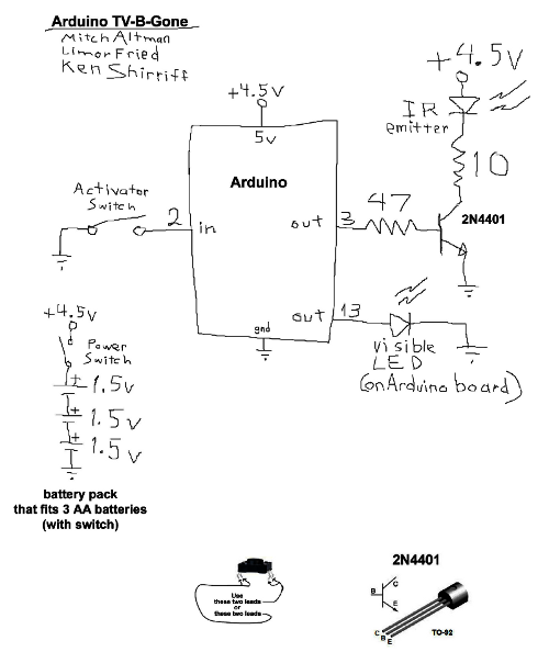
The TV-B-Gone is a compact infrared remote capable of turning off nearly any television. Previously, the TV-B-Gone software was adapted for use with the Arduino platform. For further details regarding this adaptation and its functionality, refer to the earlier...

This A/B Box pedal schematic for electric guitar was designed by Rick Barker. The A/B Box effect was originally intended for switching between different harmonica microphones. It features a low-noise dual preamp for improved performance. The A/B Box schematic serves...
This circuit demonstrates the use of Silicon Controlled Rectifiers (SCRs) to control low-voltage pulsating DC for operating homemade LED light panels. Although the circuit utilizes an Arduino, the underlying concepts are applicable to various microcontrollers, whether through hardware interrupts...
The Circuit is composed of two sections, the light sensing and the power switching. The light sensing part consists of a photo-resistor R4, connected like a voltage divider to R2. Since the resistance of the photo-resistor changes depending on...
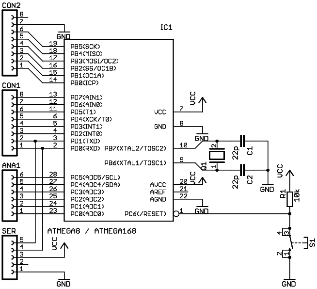
When starting with Arduino, one often accumulates more Arduino boards than RS232 or USB ports available on the computer. Therefore, it is more practical to use an external signal level converter rather than placing it directly on the Arduino...