
arduino LCD

To connect an LCD display to an Arduino, first gather the necessary components: an Arduino board (such as the Arduino Uno), a 16x2 LCD display, a breadboard, jumper wires, and a potentiometer (optional for contrast adjustment).
Begin by placing the LCD display on the breadboard. The typical 16x2 LCD has 16 pins, with the following relevant connections:
1. **Pin 1 (VSS)**: Connect to the ground (GND) of the Arduino.
2. **Pin 2 (VDD)**: Connect to the 5V power supply from the Arduino.
3. **Pin 3 (VO)**: Connect to the middle pin of a potentiometer (if used for contrast adjustment), with the other two pins connected to 5V and GND respectively. If a potentiometer is not used, this pin can be connected directly to ground for minimal contrast.
4. **Pin 4 (RS)**: This pin is for the register select. Connect it to a digital pin on the Arduino, commonly pin 12.
5. **Pin 5 (RW)**: Connect this pin to ground to set the LCD in write mode.
6. **Pin 6 (E)**: This is the enable pin. Connect it to another digital pin on the Arduino, typically pin 11.
7. **Pins 7-14 (D0-D7)**: These are the data pins. For a 4-bit mode, connect pins D4-D7 (pins 12-15) to digital pins on the Arduino (for example, pins 5, 4, 3, and 2).
8. **Pin 15 (LED+)**: Connect to 5V for the backlight.
9. **Pin 16 (LED-)**: Connect to ground.
After establishing the connections, upload a simple test sketch to the Arduino to initialize the LCD and display a message. The `LiquidCrystal` library is commonly used for this purpose. The code will set up the LCD dimensions, specify the pins used, and include commands to print text to the display.
Once the code is uploaded, power the Arduino, and the LCD should display the specified message, confirming that the connection is successful. This procedure provides a foundational understanding of interfacing an LCD with an Arduino, which can be expanded upon with more complex functionalities in future projects.How to connect a LCD display to an Arduino and test it. This tutorial shows beginners how to use a breadboard to connect an LCD display to an Arduno, step by step.. 🔗 External reference
Related Circuits
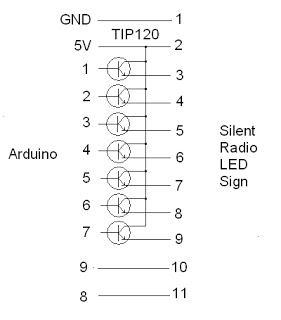
The project addresses a brightness issue with the LED display. The original design using a 4017 counter was ineffective because it lacked the capability to turn off the display while updating the shift registers. Consequently, the decision was made...
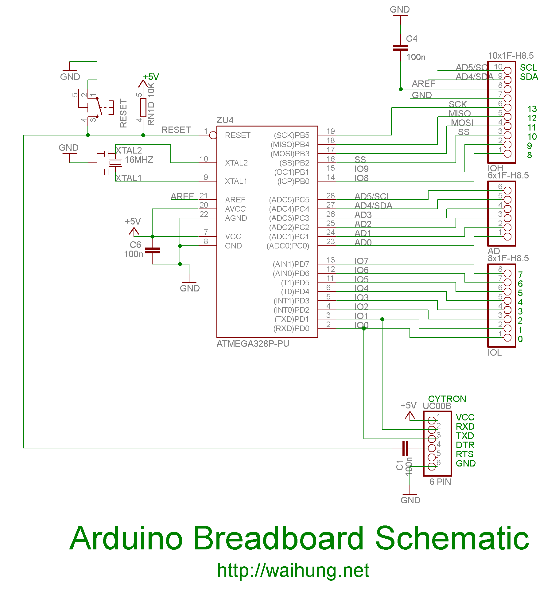
On the Uno boards, there is an integrated circuit (IC) that functions as a USB to serial converter, enabling programming and communication with the Arduino from a computer. This IC is a surface-mounted device (SMD). The R3 version utilizes...
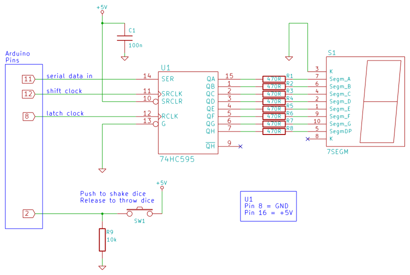
Arduino 7-segment display dice circuit and tutorial with Arduino sketch. Build a dice that is shaken by holding a button in and thrown by releasing the button. The shake, throw, and number thrown are animated and displayed on a...
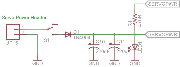
This document explains how to utilize an Arduino to control up to 12 servos simultaneously with minimal jitter. A straightforward serial interface allows for the control of the position of these 12 servo channels. Additionally, it is possible to...
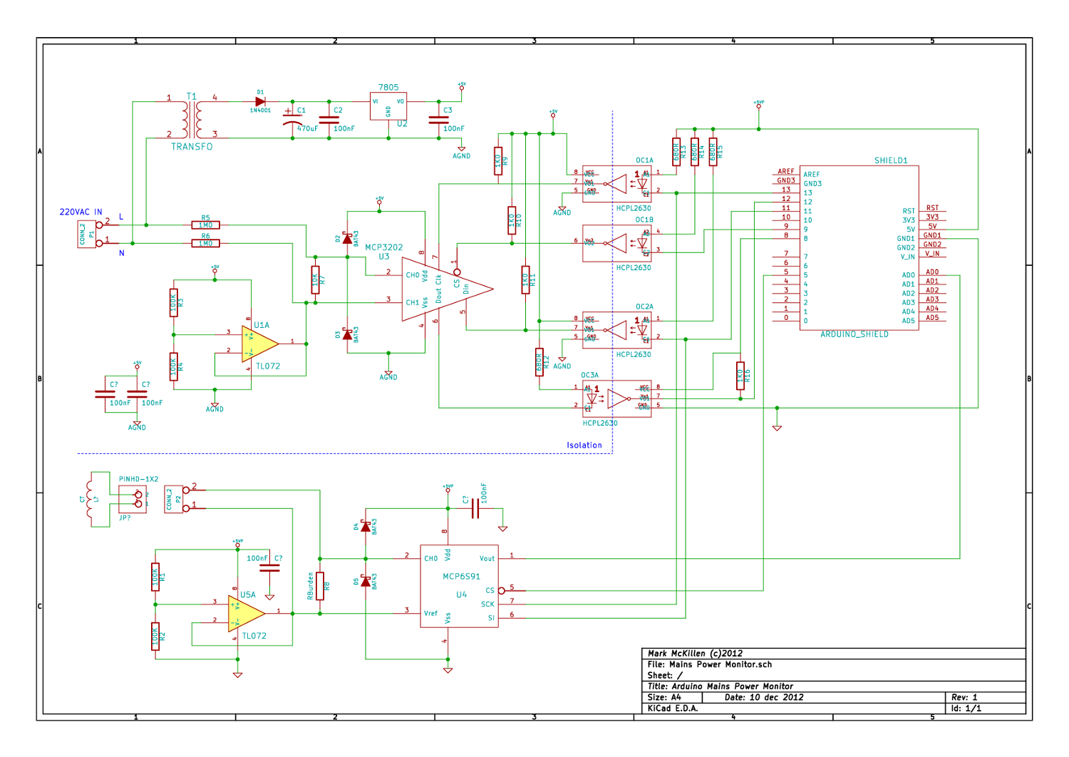
A mains (220-240VAC) power monitoring circuit has been sought for interfacing with an Arduino. While the OpenEnergyMonitor solution employs a transformer for isolation and measurement of mains voltage, it has been noted that the transformer does not couple effectively...
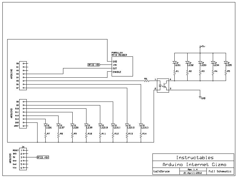
The Arduino Internet Gizmo is a USB, Arduino, and RFID device designed for web browsing. It operates by placing an RFID tag on the device, which reads the tag and transmits the tag number via USB to a program...