
arduino tiny relay shield

The tiny stripboard relay shield for Arduino is designed to facilitate the control of external devices through relay activation. This shield typically accommodates two relays, which can be utilized to switch higher voltage loads, such as lights or motors, that exceed the direct output capabilities of the Arduino.
The circuit diagram for the relay shield will illustrate the arrangement of components, including the Arduino connections, relay modules, and power supply considerations. Each relay will be connected to a digital output pin on the Arduino, allowing for individual control. The circuit may also include necessary components such as flyback diodes across the relay coils to prevent voltage spikes from damaging the Arduino when the relays are turned off.
The software component of the project will involve coding to control the relays using Arduino IDE. The code typically includes initializing the digital pins connected to the relay inputs and defining functions to turn the relays on and off based on user commands received from the PC. Communication between the PC and Arduino can be established via a serial connection, allowing users to send commands to the Arduino to execute the relay control.
This setup provides a versatile solution for automating various devices and can be expanded with additional features such as status indicators or feedback mechanisms to enhance user interaction and monitoring.Build the tiny stripboard relay shield for Arduino. View the circuit diagram and download the software. Control two relays from your PC and use your PC to switch things on and off.. 🔗 External reference
Related Circuits
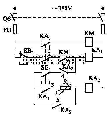
Competition among relay contacts in contactor control systems often leads to significant issues that can be cumbersome to address. In some cases, this requires the addition of numerous components. However, utilizing a negative temperature coefficient thermistor (NTC) for delay...
The schematic below illustrates 4 methods of controlling a relay with a digital logic signal. Figure (A) can probably be used in most cases where the relay coil requires 100 mA or less and the input current is 2...
The circuit below requires a double pole, double throw relay in conjunction with a single transistor to allow toggling the relay with a momentary push button. One set of relay contacts is used to control the load, while the...
To troubleshoot the headlight system, switch the headlight switch ON and OFF and check if the headlight relay can be felt and heard clicking. This is indicated in the first schematic on the left side of the diagram. The...
This document describes a PLL FM transmitter utilizing the LMX1601 and either the ATtiny2313 or AT90S2313 microcontrollers. A common feature of previous low-power FM transmitters developed over the years is that their operating frequency is determined by an LC...
This is a tutorial for beginners who have recently started learning about electronics. The author has prior experience in programming with C and Python. The schematic presented in this tutorial is designed for novice electronics enthusiasts who are transitioning from...