
PLL FM Transmitter using LMX1601 ATtiny2313 AT90S2313

The PLL FM transmitter circuit employs a phase-locked loop (PLL) architecture to achieve frequency modulation. The LMX1601 serves as the frequency synthesizer, providing a stable output frequency that is crucial for effective FM transmission. The ATtiny2313 or AT90S2313 microcontroller is used for controlling the PLL and managing the modulation process.
The operating frequency is primarily defined by the LC circuit, which consists of an inductor (L) and a capacitor (C) arranged to create a resonant frequency. This resonant frequency can be adjusted by varying the values of L and C or by using variable components such as a variable capacitor or inductor. The stability of the output frequency is enhanced by the PLL, which continuously adjusts the frequency of the LMX1601 to match the desired reference frequency, thus minimizing drift and ensuring consistent performance.
In this design, the microcontroller is programmed to handle the modulation scheme, allowing for flexibility in the transmission characteristics. The microcontroller interfaces with the LMX1601 to set the desired output frequency and can also implement additional features such as audio input processing, allowing for the modulation of audio signals onto the carrier frequency.
The circuit layout should be carefully designed to minimize noise and interference, which can affect the performance of the transmitter. Proper grounding techniques and the use of decoupling capacitors are essential to maintain signal integrity. Furthermore, the choice of components should consider the frequency range of operation, power consumption, and overall efficiency of the transmitter.
Overall, this PLL FM transmitter design represents a significant advancement over previous low-power FM transmitters, combining the stability of PLL technology with the flexibility of microcontroller programming to achieve a reliable and high-quality FM transmission.Here`s a PLL FM Transmitter using LMX1601, ATtiny2313 or AT90S2313 microcontrollers. The common characteristic of all of the previous low power FM transmitters I`ve built over the decades, is that their operating frequency is determined by an LC resonant circuit. Some of them had excellent stability, some of them didn`t, but I had always wanted to make one.. 🔗 External reference
Related Circuits
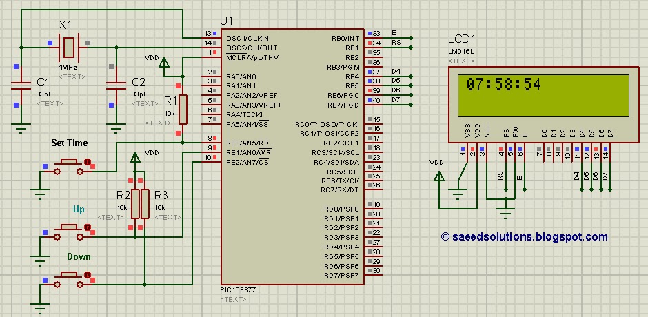
This tutorial on the PIC16F877 microcontroller addresses the question, "How to implement a controllable digital clock using the PIC16F877?" It utilizes the PIC16 simulator for demonstration purposes. The implementation of a controllable digital clock using the PIC16F877 microcontroller involves several...
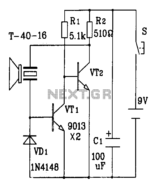
The discrete components ultrasonic transmitter circuit T/R-40-16 can emit a series of ultrasonic signals at a frequency of 40 kHz. This circuit operates at a voltage of 9V and has a current consumption of 25mA, with a control distance...
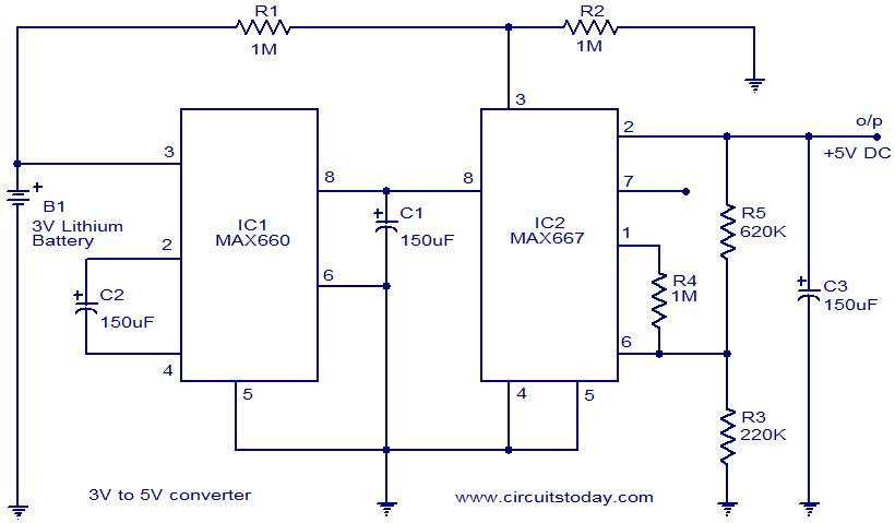
Voltage converter circuit diagram for converting 3 volts to 5 volts using CMOS monolithic ICs MAX660 and MAX667, which functions as a positive voltage regulator. The voltage converter circuit utilizes the MAX660 and MAX667 integrated circuits to step up a...
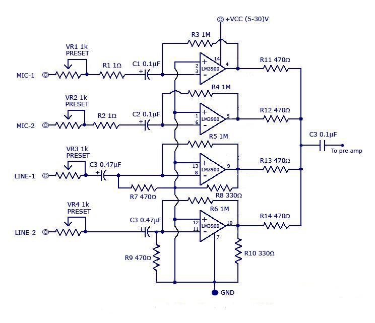
The circuit includes a quad channel amplifier (LM3900) with microphone audio inputs and direct line inputs. By adding circuits in parallel, the number of inputs can be increased for various applications. The input is connected to the inverting terminal...
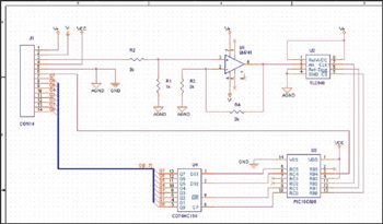
This example demonstrates the design of a circuit that incorporates both analog and digital components, features multiple power planes, and utilizes a single ground plane that is divided into analog and digital sections while maintaining a common reference point. The...

A monostable multivibrator (MMV) features one stable state and one quasi-stable state. The circuit remains in its stable state until an external triggering pulse prompts a transition to the quasi-stable state. After a designated time period T, the circuit...