
Arduino Analog Input

The described circuit utilizes a potentiometer to manipulate the blinking rate of an LED connected to an Arduino board. The potentiometer functions as a variable resistor, providing an adjustable voltage that is read by the Arduino's analog input. The connections are made as follows: the outer pins of the potentiometer are connected to the power supply (5V) and ground, while the middle pin (wiper) is connected to the analog input pin (A0) of the Arduino. This configuration allows the potentiometer to act as a voltage divider.
When the potentiometer is adjusted, it changes the voltage at the center pin, which is read by the Arduino using the analogRead() function. The Arduino's ADC converts this voltage into a digital value between 0 and 1023, corresponding to the voltage levels. The resulting digital value is then stored in the variable sensorValue.
The program uses this sensorValue to determine the delay between LED blinks. The built-in LED on pin 13 can be utilized directly, or an external LED can be added. If using an external LED, it is connected with its anode to pin 13 and cathode to ground. Given the low current output from pin 13, a current-limiting resistor is not required.
As the user rotates the potentiometer, they can observe the LED blinking at varying rates, demonstrating the relationship between resistance, voltage, and the resulting output behavior of the LED. This circuit serves as an excellent introduction to analog input reading and control of digital outputs using a simple and effective interface.A potentiometer is a simple knob that provides a variable resistance, which you can read into the Arduino board as an analog value. In this example, you`ll connect a poterntiometer to one of the Arduino`s analog inputs to control the rate at which the built-in LED on pin 13 blinks.
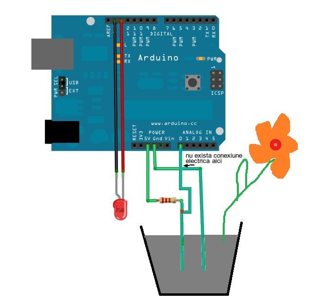
Connect three wires to the Arduino board. The first goes to ground from one of the outer pins of the potentiometer. The second goes from 5 volts to the other outer pin of the potentiometer. The third goes from analog input 0 to the middle pin of the potentiometer. For this example, it is possible to use the Arduino board`s built in LED attached to pin 13. To use an additional LED, attach its longer leg (the positive leg, or anode), to digital pin 13, and it`s shorter leg (the negative leg, or cathode) to the ground (gnd) pin next to pin 13. Because of the low amount of current coming from digital pin 13, it is not necessary to use a current limiting resistor in this particular case.
In the beginning of this program, the variable sensorPin is set to to analog pin 0, where your potentiometer is attached, and ledPin is set to digital pin 13. You`ll also create another variable, sensorValue i to store the values read from your sensor. The analogRead() command converts the input voltage range, 0 to 5 volts, to a digital value between 0 and 1023.
This is done by a circuit inside the Arduino called an analog-to-digital converter or ADC. By turning the shaft of the potentiometer, you change the amount of resistance on either side of the center pin (or wiper) of the potentiometer. This changes the relative resistances between the center pin and the two outside pins, giving you a different voltage at the analog input.
When the shaft is turned all the way in one direction, there is no resistance between the center pin and the pin connected to ground. The voltage at the center pin then is 0 volts, and analogRead() returns 0. When the shaft is turned all the way in the other direction, there is no resistance between the center pin and the pin connected to +5 volts.
The voltage at the center pin then is 5 volts, and analogRead() returns 1023. In between, analogRead() returns a number between 0 and 1023 that is proportional to the amount of voltage being applied to the pin. That value, stored in sensorValue, is used to set a delay() for your blink cycle. The higher the value, the longer the cycle, the smaller the value, the shorter the cycle. 🔗 External reference
Related Circuits
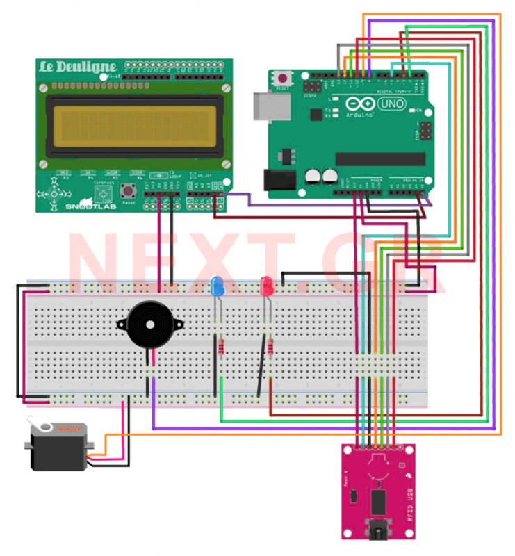
This project aims to develop a security system suitable for business environments or for simple home use. The system utilizes an Arduino Uno microcontroller in conjunction with RFID (Radio Frequency Identification) technology, enabling wireless user identification. Only registered users...
The analog computer was initially simulated using Multisim 7. Following this, an analog simulator circuit was constructed on breadboards using discrete and integrated components. A function generator was utilized to provide the road surface as input, and the output...
This is a simple Arduino project for a soil moisture sensor that will light up an LED at a certain moisture level. It uses the Arduino Duemilanove microcontroller. This project employs a soil moisture sensor to monitor the moisture content...
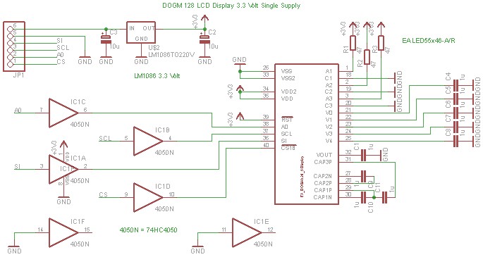
The DOGM graphics module should be connected to the Arduino board as illustrated. Pin 12 (MISO) of the Arduino board must remain unused. Furthermore, the DOGM graphics module requires an address line (A0), which can be connected to any...
This circuit is designed for dimming devices powered by transformer-based power supplies, specifically those operating at 12, 24, or 48 volts, rather than standard 120 volts. The project involves various components, including a soldering iron, wire strippers, breadboard or...
Scopeclock is a user-friendly hardware device designed to enhance the functionality of X-Y capable analog oscilloscopes. This hardware allows for the conversion of an analog oscilloscope into a scope clock. The project was developed by a team at CEDT...