
arduino yogurt maker
The described circuit employs a microcontroller, typically an Arduino, to automate the yogurt-making process by controlling a relay that powers a crock pot. The system includes a thermistor as the temperature sensor, which is critical for monitoring the temperature of the milk during the yogurt preparation. The microcontroller reads the thermistor’s resistance through a voltage divider circuit, translating it into a temperature value using the Steinhart-Hart equation, which requires specific coefficients for accurate temperature calculation.
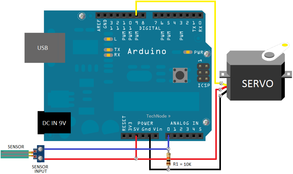
The relay serves as a switch that toggles the power to the crock pot based on the temperature readings from the thermistor. The relay's Load 1 and Load 2 connections are wired to the black wire of the extension cord, allowing for safe control of the line voltage. The ground connection is essential for safety, and the use of a project enclosure is crucial to protect users from electrical hazards.
To ensure the thermistor operates effectively within the water bath, it is encapsulated in a waterproof housing. The construction of this housing is vital for maintaining accurate temperature readings without compromising the sensor's functionality. The use of heat-shrink tubing and aluminum tubing provides a reliable method to protect the thermistor from moisture while allowing it to measure water temperature accurately.
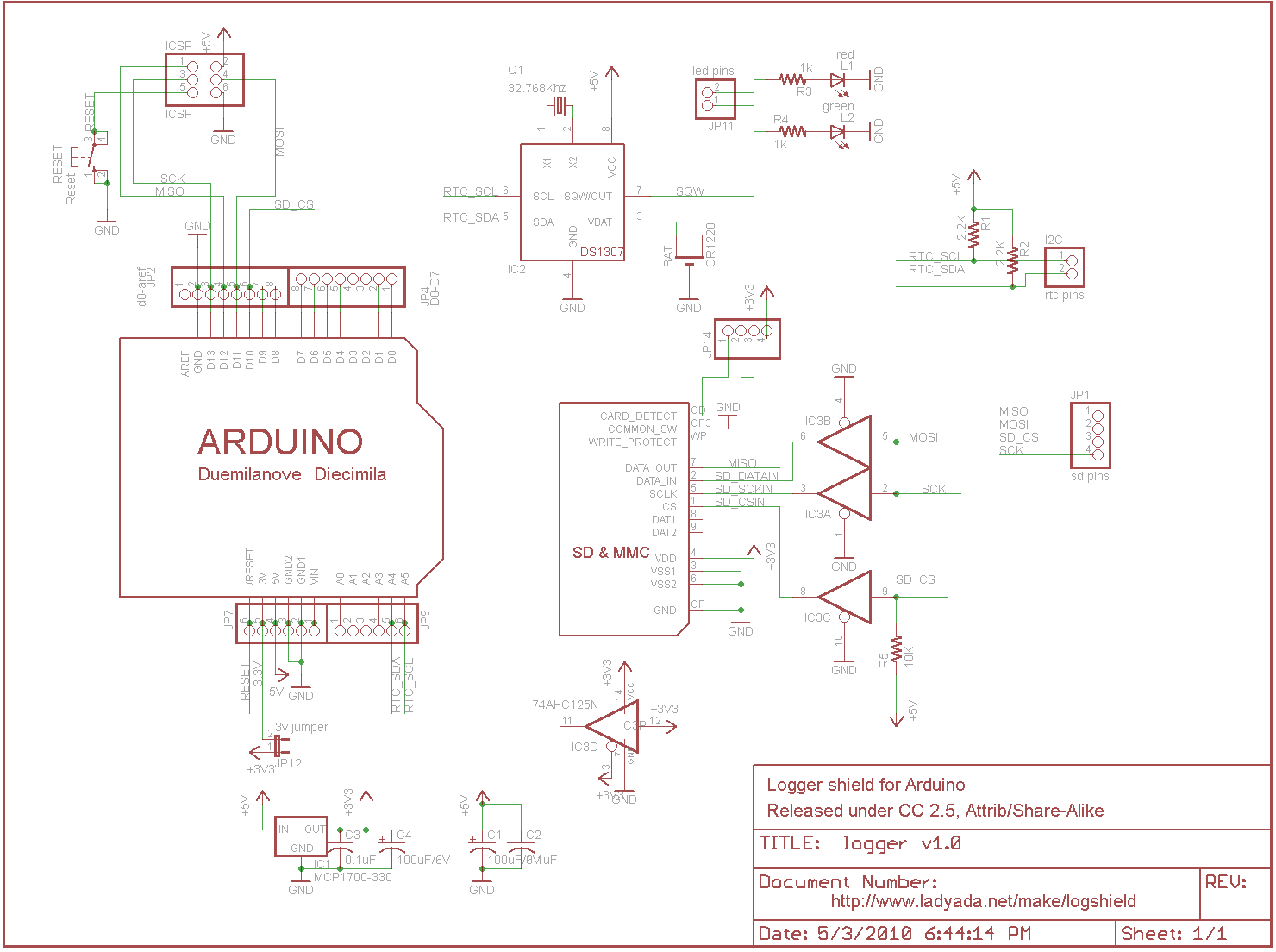
The schematic representation of this setup would typically include the microcontroller, relay, thermistor, and connections to the power supply. The visual representation aids in understanding the layout and operation of the circuit, making it accessible for individuals with varying levels of expertise in electronics. Overall, this automated yogurt-making system simplifies the process while ensuring precise temperature control, enhancing the efficiency and convenience of yogurt preparation at home.The crock pot is attached to a relay that can switch it on or off. The relay is toggled by a microcontroller based on readings from a temperature sensor ( thermistor ) placed inside the crock pot. Heat the milk to 185 °F (85 °C). This kills off microbes to make way for our yogurt cultures, and denatures enzymes in the milk that may interfere with
yogurt culture growth. Doing things the old-fashioned way, I`d be using a stovetop and candy thermometer for steps 2 and 3, then a warm oven or a radiator for step 4. That takes a lot of attention, and uses more containers than I care to wash later. Many commercially-sold yogurt makers still require you to perform step 2 yourself. With the Arduino setup, I use a few canning jars in a water bath inside the crock pot to ensure even heating.
I submerge the temperature sensor in the water. A voltage divider circuit is used to indirectly measure the resistance of the thermistor. In the code, I make use of the Steinhart-Hart Thermistor Equation to translate the thermistor`s resistance into temperature. This gives a pretty good idea of the temperature inside the crock pot. In addition to the thermistor`s resistance at a given time, the Steinhart-Hart equation needs to be fed three coefficients which can be calculated from information on the manufacturer`s data sheet based on predetermined resistances at different temperatures.
Since we`ll be measuring a range between 100 °F (38 °C) and 185 °F (85 °C), I used resistance values measured at 86 °F (30 °C), 140 °F (60 °C) and 194 °F (90 °C) to calculate my coefficients. Here`s a simple calculator to calculate your coefficients from a given temp/resistance range, and here`s a more in-depth explanation of the math involved.
Since the temperature readings will be taken in the water bath, we need a way to keep the thermistor from getting wet. Here`s a good reference for constructing a waterproof sensor. I constructed my waterproof thermistor by first soldering the thermistor onto two long (~3 ²) lead wires, then wrapping the exposed wires with heat-shrink tubing.
I slid a short length of aluminum tubing over the sensor, then used moisture-resistant shrink tubing to seal both ends. You could also use epoxy. I deviated slightly by using a female connector instead of a GFCI outlet. Use the extension cord`s male end with about 12 ³-14 ³ of cord attached. Expose the three extension cord wires in the middle of the cord`s length. Cut the black wire and solder the ends to the relay board`s Load 1 and Load 2 connections. This is where the line voltage toggles on and off. The three wires on the end of the cord attach to the female connector. The extension cord`s green/blue wire attaches to the green screw terminal. This is the ground wire. The black and white wires attach to the other two screw terminals. Use a connectivity tester to make sure that the larger slot receptacle is connected to the larger prong on the plug.
Be careful when working with line voltage, as it can kill you. The solder points on the relay are basically live exposed wires, so use a project enclosure of some sort to keep the relay from accidentally being touched. I used a discarded plastic petroleum jelly container. Diagrams and schematics for the Arduino-controlled crockpot yogurt maker are shown below. If you haven`t yet, I`d also recommend checking out Fritzing, an open-source, cross-platform development a tool that allows users to document and share their electronics prototypes.
Fritzing offers a visual mode that allows circuits to be documented as they look in real life. This is a great feature for those of us who aren`t electrical engineers, or are just visual thinkers. The best part is that the visual mode is linked to a schematic drawn with traditional electronics symbols, which can really help electronics newbs to see the translation between visual circuit layout and schematic layout.
/* Arduino-controlled crockpot t 🔗 External reference
Related Circuits
The Arduino microcontroller board can supply a current of 40mA from its output connections, with digital outputs fixed at 5V for "ON" and 0V for "OFF." This current is suitable for LEDs, but devices like motors, solenoids, and high-brightness...
As a fully-featured Linux computer, many external programmers can be used with the Raspberry Pi to program the Atmel AVR range of microprocessors. It is also possible to utilize the general-purpose input/output lines (GPIOs) found on the Raspberry Pi...
After completing the prototype and ensuring the sketch functions correctly, it is time to construct the circuit. The aim is not to provide a detailed explanation of how to create printed circuit boards, but rather to offer a general...
Part fill valves are commonly utilized in rainwater tanks. The valve activates when the water level in the tank drops to a low position. Part fill valves play a crucial role in the management of water levels in rainwater harvesting...
The board features a small power supply that generates 3.3V at 250mA. The built-in 3.3V regulator on the Arduino is not utilized because it is only guaranteed to provide up to 50mA, which may not be sufficient for some...

This Arduino-based project involves constructing a lamp with various light displays, including a color sequencer, dimming light, color chaser, and firelight, all controlled by a touch bar on the circuit board. The design adopts a minimalist approach, incorporating only...