
arduino volt ammeter final part printed

The construction of a printed circuit board (PCB) involves several critical steps, each contributing to the overall functionality and reliability of the final product. Initially, the schematic diagram serves as the blueprint for the circuit, detailing the connections and components required for operation. The choice of design software, such as CadSoft Eagle, facilitates the creation of this schematic with access to a vast library of components, which is essential for accurate representation and design efficiency.
Following the schematic design, the next phase is converting this diagram into a physical PCB layout. This involves arranging the components on a virtual board and routing the traces that will connect them. The layout must consider factors such as trace width, spacing, and the overall size of the board to ensure electrical integrity and manufacturability. The use of libraries like SparkFun enhances this process by providing readily available footprints for components, reducing design time and errors.
Once the PCB layout is finalized, the method of transferring the design onto the copper-clad board must be selected. The heat transfer method using Press-n-Peel paper has proven effective due to its ability to protect the copper during the etching process. This method requires precision in handling, as any damage to the film can result in incomplete transfers and necessitate additional attempts.
After the toner transfer, the etching process can proceed. The board is submerged in an etching solution, which removes the unprotected copper, leaving only the desired circuit traces. Post-etching, the board must be cleaned thoroughly to remove any residual etching solution and toner.
Drilling holes for component leads is the next step, where precision is paramount to ensure that the holes are appropriately sized for the components being used. The use of a Dremel rotary tool can facilitate this process, but care must be taken to select the correct drill size to avoid damaging the board or compromising the integrity of the traces.
Finally, to prevent oxidation and corrosion, the board is tinned. This process involves applying a thin layer of solder to the copper pads and traces, ensuring long-term reliability. While this can complicate soldering due to the tendency of the solder to pull away, it is a necessary step for maintaining the board's functionality over time.
In conclusion, the creation of a PCB from an Arduino project involves careful planning, precise execution, and a good understanding of the materials and methods involved. Each step, from schematic design to final assembly, plays a crucial role in the successful operation of the electronic circuit.After all job of building the prototype and making the sketch work, it`s the time to build the circuit. It`s not the objective to explain in detail how to make printed circuit boards, but only a superficial explanation about it, besides, of course, to present the project changes to make it works out of Arduino board.
Board designs are made with sp ecialized softwares. There are several available, including for free. In this project I prefered to use the CadSoft Eagle given it`s components library size available on the web, an interesting tip is also download the SparkFun components library that appear to have all components that they sell, a wide variety, and can save a big drawing time. The schematic is a circuit logical view that is a prerequisite for drawing the tracks and validate it later.
Basically the requirements to run an Arduino project on an independent printed circuit board is a 5v power supply, a 16Mhz crystal oscillator, and, of course, link the microcontroller pins with all digital and analog ports of Arduino board. The diagram bellow is popular on web and explain how we need to draw the schematic to work as the prototype.
It`s not the objective of this article to teach anyone to etch copper boards, for that there are several articles out there. But I`d like to make some important considerations. The method used for this project was the heat transfer with clothes iron. I tried before to transfer the printer toner directly as explained in some articles out there. But as each printer has it`s own characteristics is almost impossible determine a procedure that works in most cases, not to mention the various irons types and board sizes to be transferred.
It`s also notable the copper deterioration of the printed parts, which suggests that the transferred toner does not properly protect the copper during corrosion. The solution found that worked better in this method was through Press-n-Peel paper. The blue polyester film is transferred together with the toner creating an optimal etching protection, as well as it`s is removed much more easily when compared to using only toner in couche paper (or magazine paper).
But make no mistake, it`s not a trivial process and may also cause some waste with unsuccessful attempts. It`s even recommended very careful handling with it because the blue pellicle is very delicated and any bend or scratching can remove it easily (I learned the hard way) and destroy the paper (that is not cheap).
To cut and drill the board was used a Dremel 300 rotary tool attached to Workstation. We used a 1mm drill for all holes, but note that it was not very suitable for all components and opened so much some islands eliminating almost all their contact, which complicates a lot the soldering process. In such cases it`s important to use an appropriate bundle of CNC drills. In order to save the board from rust it was all tinned. This procedure makes the placement of components a little complicate, because it pulls the tin, but it is important to keep the board if it has no solder mask.
As you can see, the tinned visual is not the best: 🔗 External reference
Related Circuits
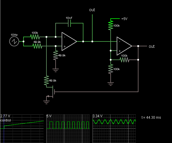
This circuit is a voltage-controlled oscillator, which is an oscillator whose frequency is determined by a control voltage. A 10 Hz sawtooth oscillator provides the control voltage in this case; this causes the frequency to rise slowly until it...
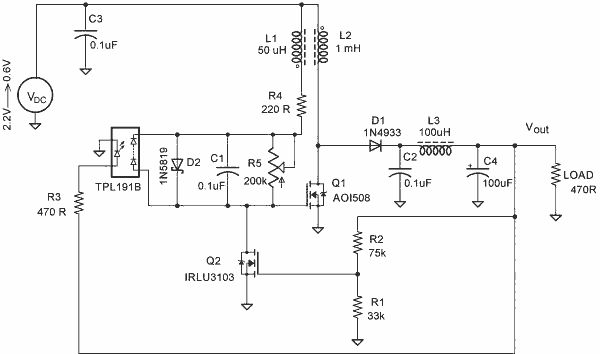
A simple blocking oscillator circuit can be utilized to increase voltage by leveraging the properties of coil inductance (V = L di/dt). Such a circuit is illustrated in Figure 1. The blocking oscillator circuit is a type of oscillator that...
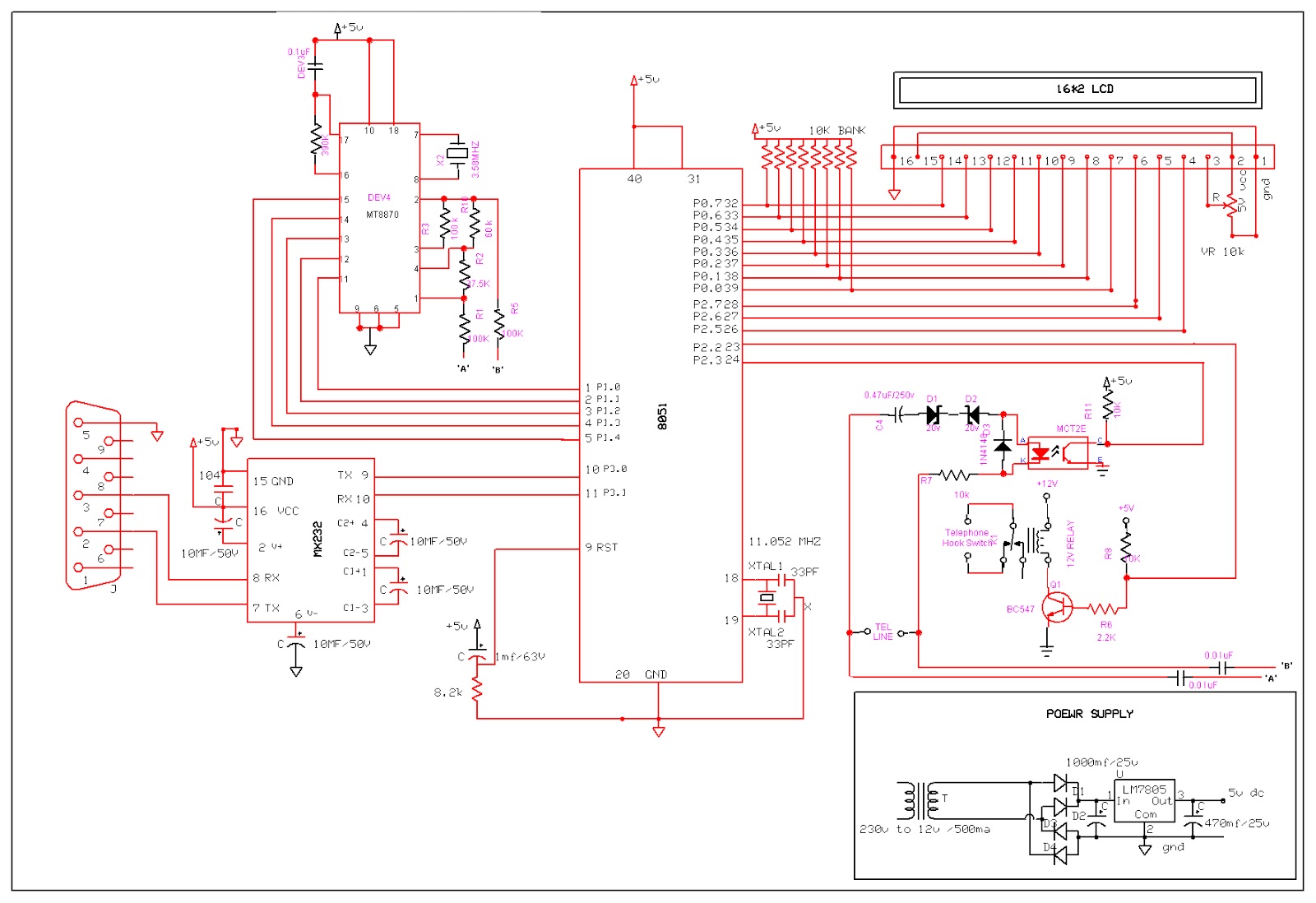
An Interactive Voice Response (IVR) system is a communication system that enables automated telephone call access to specific computer database information. This technology allows a computer to detect DTMF (Dual-tone multi-frequency) keypad inputs and generate voice responses based on...
This circuit enables a smaller control voltage to inversely and linearly control a larger output voltage (Vo). Additionally, the supply voltage (Vsp) for the operational amplifiers can be lower than the output voltage, allowing the circuit to theoretically control...
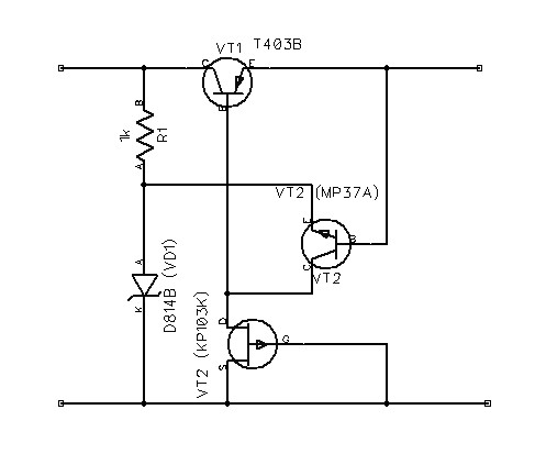
The schematic diagram originates from a voltage regulator circuit utilizing a Field Effect Transistor (FET) power supply. This circuit features a feedback mechanism involving the FET VT3, which functions as a dynamic load for transistor VT2. This configuration enhances...
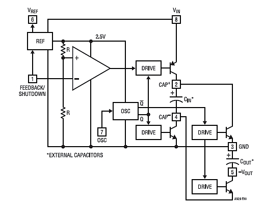
Chapter 4, part five of a five-part series titled "Some Thoughts on DC/DC Converters," authored by the late Jim Williams and Brian Huffman, is included in Volume II of the book "Analog Circuit Design-- Immersion in the Black Art...