
Astable and Monostable Multivibrators

Multivibrators can be categorized into three primary types: astable, monostable, and bistable. Each type has distinct operational characteristics and applications within digital circuits.
Bistable multivibrators, or flip-flops, are crucial for data storage and transfer in digital systems. They maintain one of two stable states until an external trigger causes them to switch states. The most common types of flip-flops include SR (Set-Reset), JK, D (Data), and T (Toggle) flip-flops.
In an SR flip-flop, two inputs, Set (S) and Reset (R), control the output states. When the Set input is activated, the output Q becomes high, while the Reset input sets Q low. The JK flip-flop enhances the functionality of the SR flip-flop by allowing both inputs to toggle the output state based on the clock signal. The D flip-flop captures the value of the D input at a specific clock edge, providing a simple mechanism for data storage. The T flip-flop toggles its output state with each clock pulse, making it ideal for frequency division applications.
The implementation of these flip-flops is typically achieved using various logic gates, such as NAND or NOR gates, to construct the desired behavior. The choice of gate type influences the propagation delay, power consumption, and overall performance of the multivibrator.
In summary, multivibrators are integral components in digital electronics, with bistable multivibrators playing a pivotal role in memory and data handling applications. Their ability to maintain stable states and respond to input signals makes them essential in designing sequential circuits, counters, registers, and memory devices.Multivibrators is two state devices which is used extensively in digital electronics. The bistable multivibrators or called filp-flop are the basic memory.. 🔗 External reference
Related Circuits
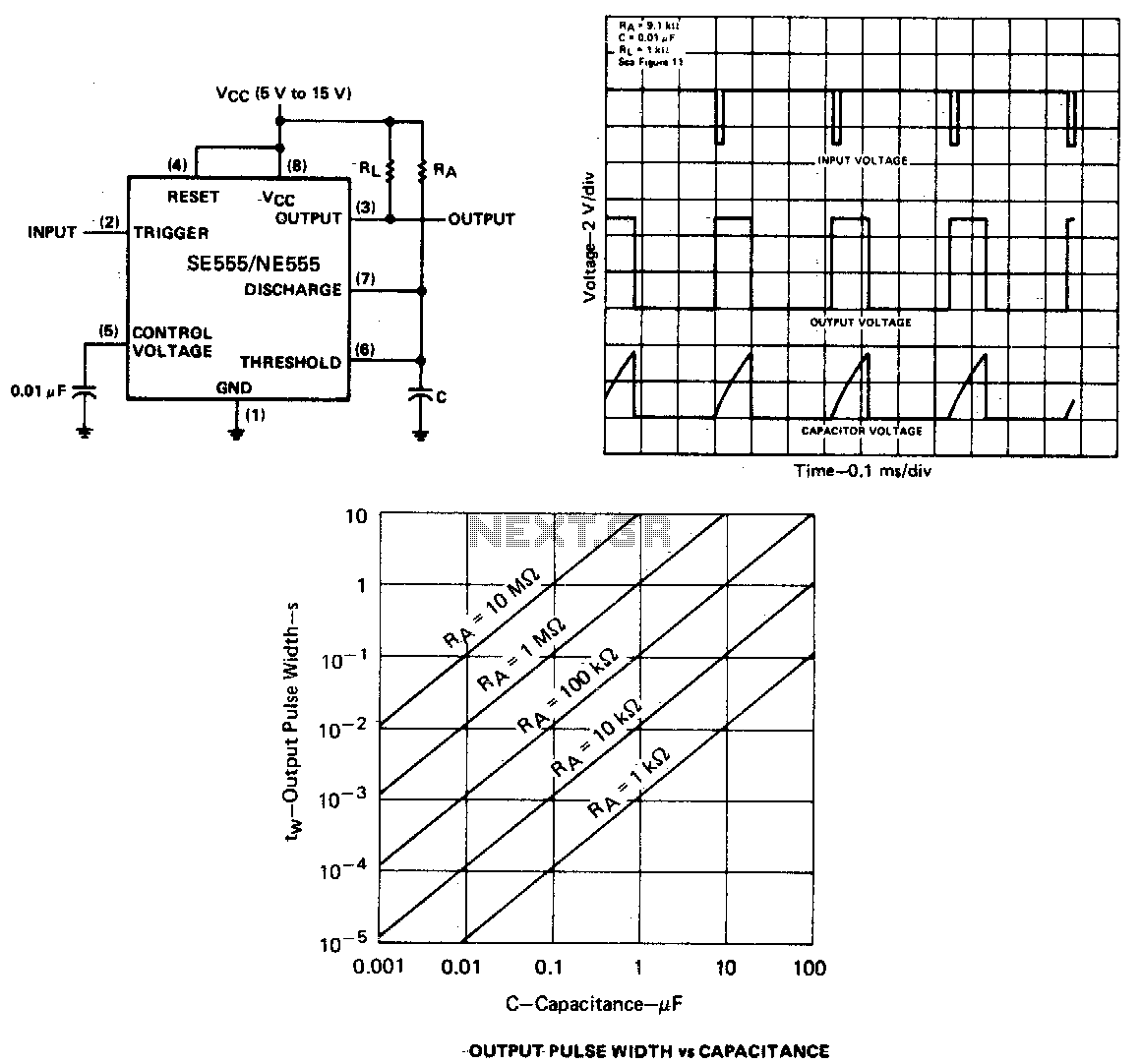
When the output is low, applying a negative-going pulse to the trigger input sets the flip-flop (Q goes low), driving the output high and turning off component 1. Capacitor C is then charged through resistor Ra until the voltage...

A multivibrator that generates its own square waves without requiring an external trigger pulse is known as an astable multivibrator. This circuit is also referred to as a free-running multivibrator. It lacks a stable state and instead oscillates continuously between...
This circuit is straightforward. The initial 555 timer prevents the second timer from being activated while the first is operational. Drive the circuit with a simple 12-volt power supply. The circuit utilizes two 555 timer integrated circuits (ICs) configured in...
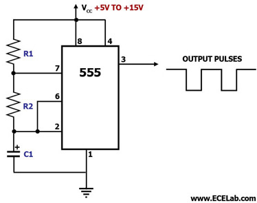
This circuit diagram illustrates the configuration of a 555 timer integrated circuit (IC) as an astable multivibrator. An astable multivibrator is a timing circuit characterized by unstable 'low' and 'high' states. Consequently, the output of an astable multivibrator continuously...
What exactly is a multivibrator? I suppose one definition would be 'a circuit which has several states'. This will do for now, it's quite loose so leaves plenty to the imagination! Conventional multivibrators have only two stages and come...
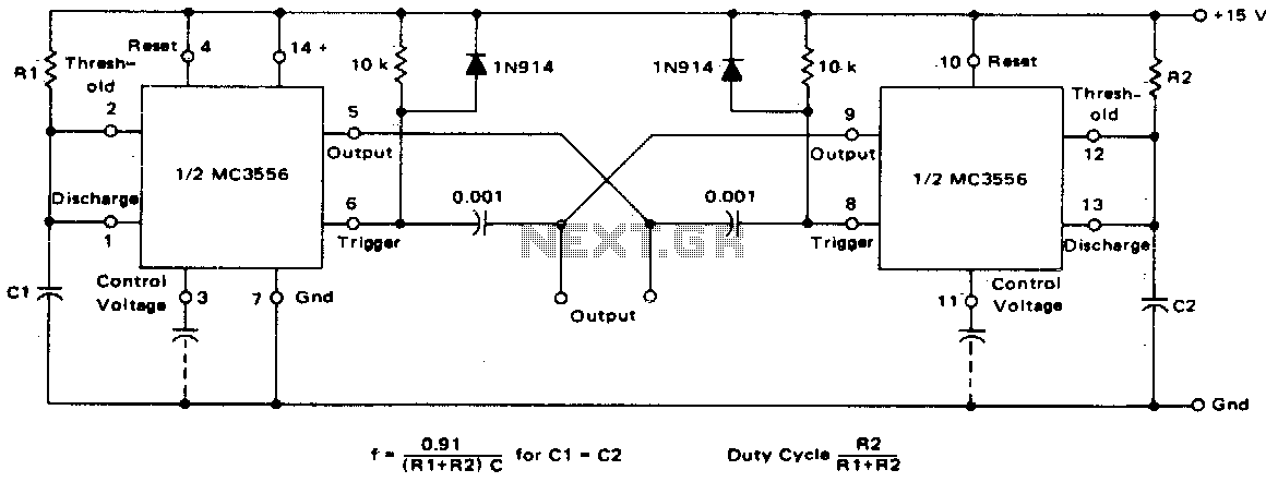
This dual astable multivibrator offers versatility not found in single timer circuits. The duty cycle can be adjusted from 5% to 95%. The two outputs generate two-phase clock signals, which are frequently required in digital systems. Additionally, it can...