
Astable

The astable multivibrator circuit is a fundamental building block in electronic design, commonly utilized in timer applications, pulse generation, and waveform generation. In this configuration, the astable multivibrator operates without requiring any external triggering, generating a continuous square wave output.
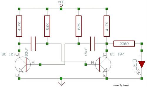
In this circuit, the external capacitor (C) plays a critical role in determining the timing characteristics of the oscillation. The resistors RA and RB are configured in such a way that they control the charging and discharging paths of the capacitor. During the charging phase, current flows through both resistors RA and RB, allowing the capacitor to accumulate voltage. The time taken for the capacitor to charge to 2/3 Vs is primarily dictated by the values of RA and RB, as well as the capacitance value of C.
Once the voltage across the capacitor reaches 2/3 Vs, the output state of the multivibrator changes, causing the capacitor to discharge through resistor R8. The discharge phase is quicker compared to the charge phase, with the time taken to drop to 1/3 Vs being influenced solely by R8. This design choice ensures that the duty cycle can be precisely adjusted by manipulating the values of RA and RB, while the discharge path through R8 remains constant.
The frequency of oscillation, which is critical for applications requiring precise timing, is given by the formula derived from the charge and discharge times. Notably, the independence of frequency from supply voltage makes this circuit particularly robust in varying power supply conditions, ensuring consistent performance across different operating environments.
The graphical representation of frequency versus RA, RB, and C provides valuable insight into how changes in these components will affect the output frequency. Engineers can utilize this information to tailor the multivibrator's performance to meet specific application requirements, whether for generating clock pulses, tone generation, or flashing LED indicators.
In summary, this astable multivibrator circuit exemplifies a versatile and reliable method for generating oscillating signals, with its performance finely tunable through the selection of passive components.This astable will trigger itself and run free as a multivibrator. The external capacitor charges through RA and RB and discharges through R8 only. Thus, the duty cycle is set by the ratio of these two resistors, and the capacitor charges and discharges between 1/3 Vs and 2/3 Vs. The charge and discharge times, and therefore frequency, are independent of supply voltage. The free-running frequency versus RA, RB and C is shown in the graph.
Related Circuits
An astable multivibrator is a switching circuit that alternates its output on and off for a designated time period. This device, also known as a free-running oscillator circuit, is primarily utilized to generate square waves over a specified duration....
A variable frequency, variably duty cycle 555 configuration is set up in astable mode. A set of potentiometers is utilized to achieve a wide range of control. The output is functioning well; however, there is an issue. The circuit...
This calculator computes the resistor and capacitor values for a NE555 timer chip configured as an astable multivibrator (oscillator) or square wave generator. By entering the desired duty cycle and frequency, the calculator provides suitable values for the resistors...
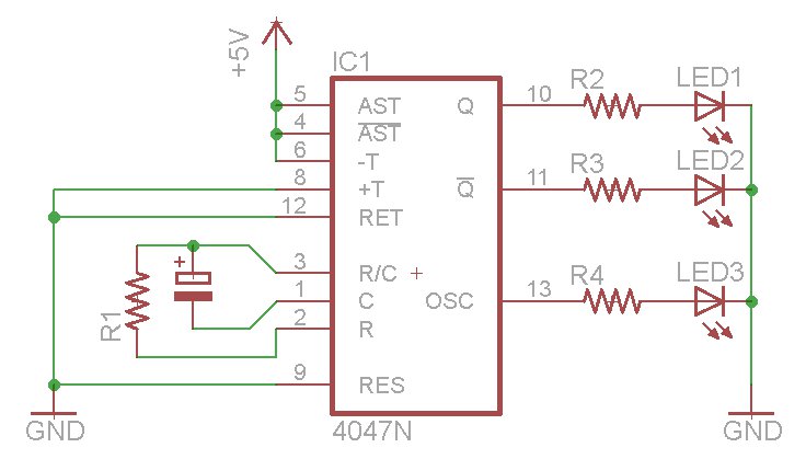
The oscillator output generates a signal that is approximately twice the frequency of Q. The other pins will be considered subsequently. In a brief video demonstration, LEDs are connected to all three outputs, illustrating the alternating behavior of Q...
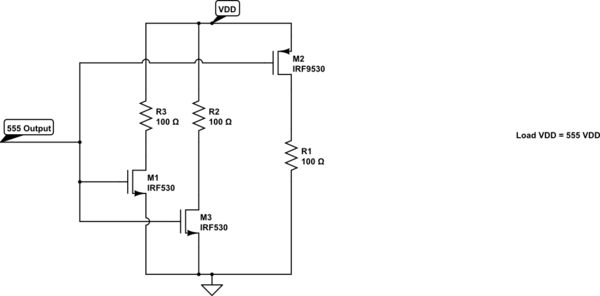
A square wave generator with a variable frequency and a 50% duty cycle is required. While the 555 timer is a common choice, the standard astable multivibrator configuration alters the duty cycle when the frequency is adjusted. A circuit...
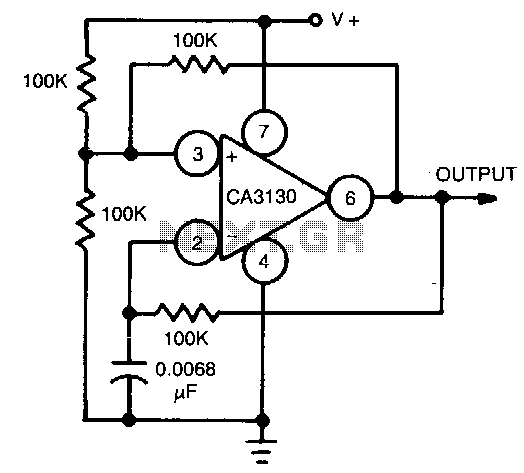
This circuit utilizes the CA3130 BiMOS operational amplifier, which operates at a frequency of 1 kHz. It features a rail-to-rail output swing, ensuring that the output can reach the supply voltage levels. The frequency of operation remains independent of...