
NE555 Astable Multivibrator Frequency and Duty Cycle Calculator

The NE555 timer is a versatile integrated circuit widely used in various applications, particularly in generating precise timing and oscillation. When configured as an astable multivibrator, the NE555 produces a continuous square wave output, making it ideal for applications such as clock pulses, tone generation, and LED flashing.
In the astable mode, the NE555 operates without any stable state, continuously switching between high and low output states. The frequency of oscillation and the duty cycle are determined by two resistors (R1 and R2) and a capacitor (C1) connected to the timer's pins. The output frequency (f) can be calculated using the formula:
\[ f = \frac{1.44}{(R1 + 2R2) \cdot C1} \]
The duty cycle (D) is defined as the ratio of the time the output is high to the total period of the output signal. It can be calculated using the following equation:
\[ D = \frac{R2}{R1 + 2R2} \]
To utilize the calculator effectively, the user inputs the desired frequency and duty cycle. The calculator then uses these parameters to derive the values for R1, R2, and C1, ensuring that the output meets the specified requirements. This process involves iterative calculations, adjusting component values until the desired frequency and duty cycle are achieved.
It is essential to select standard resistor and capacitor values to ensure availability and practical implementation. Additionally, considerations for tolerances and temperature coefficients of components may influence the final design, particularly in precision applications. The NE555 timer's output can drive various loads directly or may require additional driver circuitry, depending on the application's power requirements.This calculator computes the resistors and capacitors for a NE555 timer chip, which has been configured as a astable multivibrator (oscillator), or square wave generator. Just enter in the duty cycle and the frequency and the calculator will compute reasonable values for the resistors and capacitors.
🔗 External reference
Related Circuits
Camping today often requires various electronic devices for daily activities and entertainment. Typically, a charged lead-acid battery and a power inverter are utilized to ensure a well-organized trip, allowing family members to enjoy their electronic equipment. It is essential...
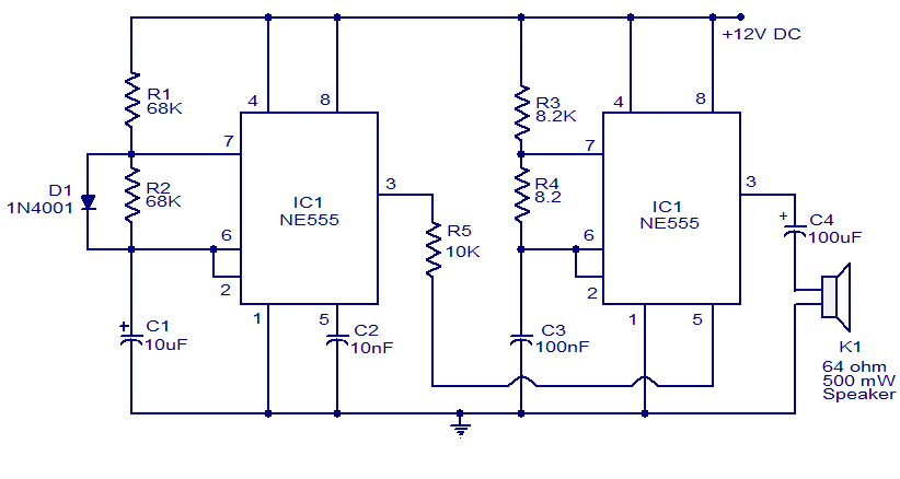
A variety of electronic circuits utilize the NE555 timer integrated circuit (IC). The circuit diagram presented illustrates a police siren based on two NE555 timer ICs, both configured as astable multivibrators. The circuit operates on a DC voltage supply...
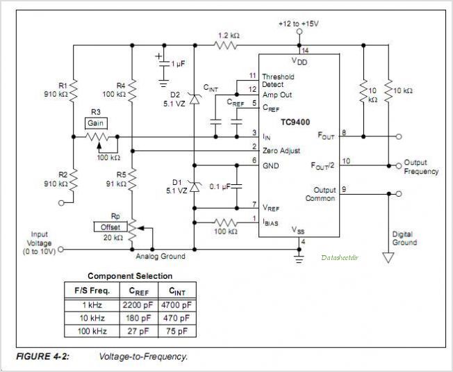
The TC9400, TC9401, and TC9402 are low-cost voltage-to-frequency (V/F) converters that utilize low-power CMOS technology. These converters accept a variable analog input signal and generate an output pulse train, with a frequency that is linearly proportional to the input...

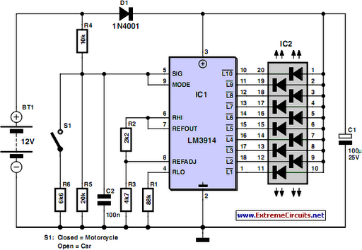
This circuit features a LED sequencer/chaser utilizing the CD4017 and NE555 integrated circuits (ICs). The CD4017 is a CMOS counter IC with 16 pins, providing 10 outputs based on the clock pulses received at its clock input, pin 14....

An NE555 timer integrated circuit (IC) configured in a specific manner can identify the absence of a pulse or an unusually long duration between two successive pulses in a pulse train. Such circuits are applicable for detecting the intermittent...
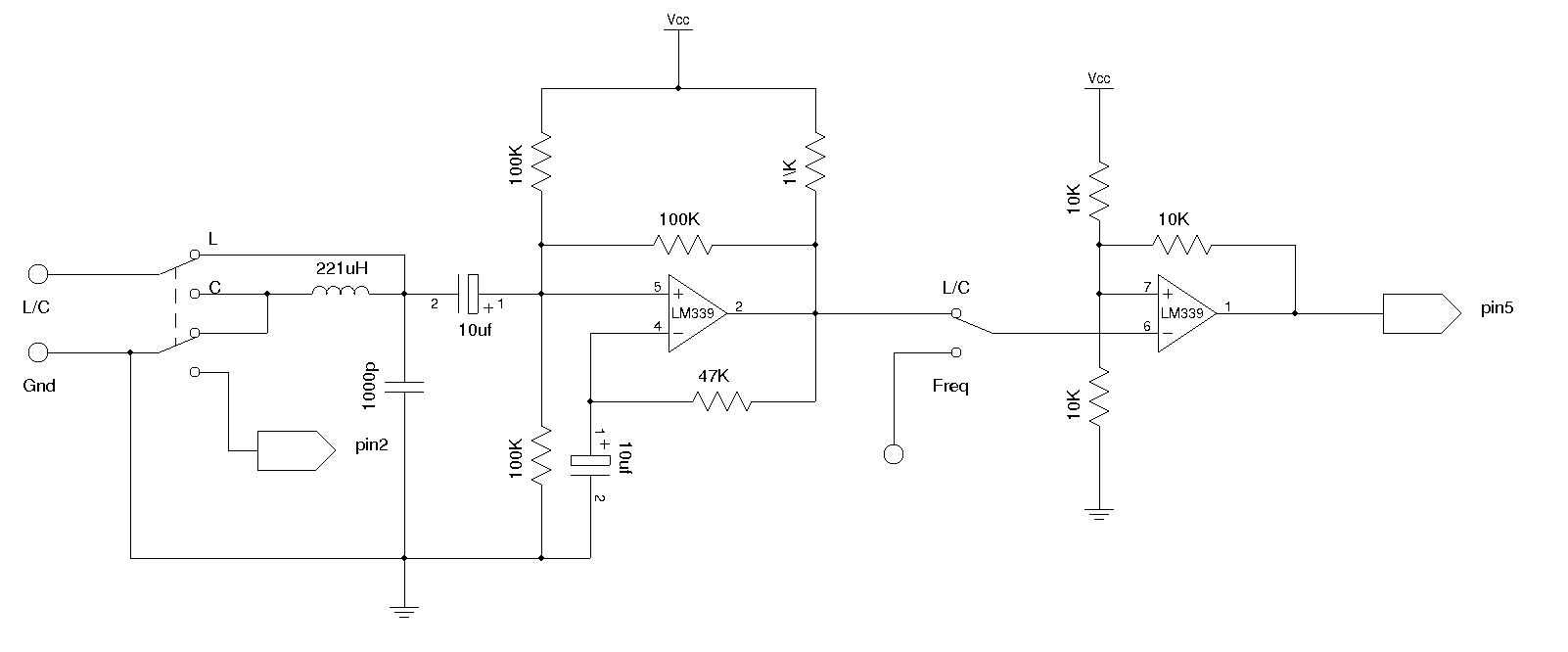
An LC meter is being constructed due to the absence of a multimeter capable of measuring inductance. Although the available multimeters can measure capacitance, they lack accuracy for small capacitance values in the range of several picofarads (pF). While...