
Asynchronous counter circuit and the signal waveform

An asynchronous counter, also known as a ripple counter, is a digital circuit that counts in binary without relying on a common clock signal to trigger all flip-flops simultaneously. Instead, each flip-flop in the counter is triggered by the output of the preceding flip-flop, resulting in a ripple effect. This characteristic allows for the design of counters that can operate independently or in applications where precise timing is not critical.
The basic configuration of an asynchronous counter typically involves a series of flip-flops (commonly T or JK flip-flops) connected in a cascading manner. The first flip-flop is usually triggered by an external input signal, while each subsequent flip-flop is triggered by the output of the previous one. As a result, the output state of the counter changes in response to the input signal, with a delay introduced by the propagation time through each flip-flop.
The primary advantage of an asynchronous counter is its simplicity and ease of implementation, as it does not require a centralized clock signal. This feature makes it suitable for applications where the speed of operation is less critical, and cost-effective solutions are desired. However, the main drawback is that the propagation delay can lead to inaccuracies in counting at higher frequencies, as the ripple effect can cause the output to change in a non-uniform manner.
In practical applications, asynchronous counters are often used in digital clocks, frequency dividers, and event counters, where the counting does not need to be synchronized with a clock signal. The design of such counters can be tailored to meet specific requirements, such as counting in binary, BCD (Binary-Coded Decimal), or other number systems, depending on the configuration of the flip-flops and the logic circuitry employed. Asynchronous counter shown, this circuit no clock synchronization signal can be used in a random counter or independent unit circuit.
Related Circuits
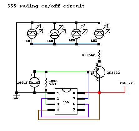
A circuit was constructed based on an LED beating heart frame instructable, but it is not functioning as expected. There is also mention of a built LED sequencer. The LED beating heart circuit typically involves a microcontroller, such as an...
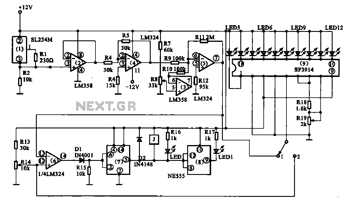
Vegetable greenhouse temperature detection control circuit. The greenhouse temperature detection control circuit is primarily composed of a temperature sensor SL234M, operational amplifiers LM324 and LM358, a dual time base circuit NE555, a relay, and a display driver circuit. The...
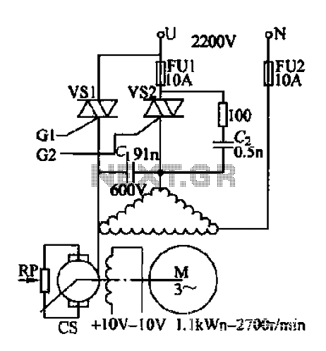
AC voltage is rectified by a bridge (VD1-VD4). A resistor (R1) limits the buck, while diode (VD5) provides clipping. A trapezoidal wave is generated as the trigger circuit for DC voltage and synchronization. When the base of transistor (VT1)...
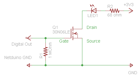
The process of driving an LED involves using a Power MOSFET to control the LED's state (On and Off) via a digital signal. This guide provides a step-by-step approach to wiring the circuit on a breadboard, which serves as...
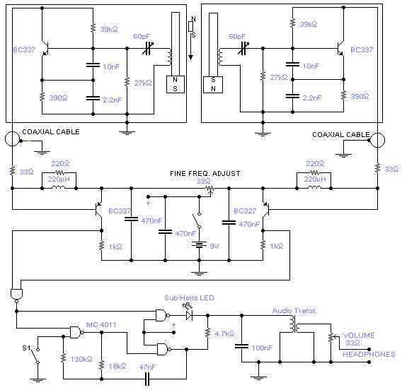
This is a rather sensitive circuit which will detect minute variations of a magnetic field, particularly the Earth magnetic field. The principle is based on an audio beat tone generated by two identical oscillators. These must be built in...
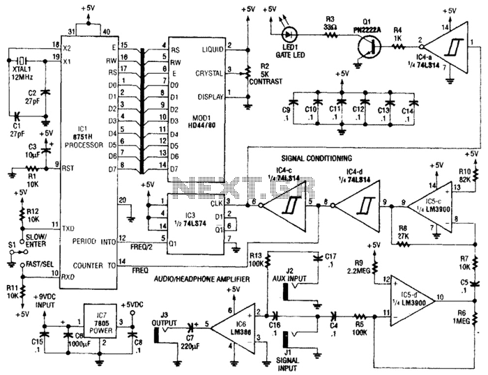
Perfect Pitch, which is based on the 8751 microprocessor, is an affordable and straightforward instrument tuner and frequency counter that features a built-in headphone amplifier and a visual metronome. Perfect Pitch converts the audio signal from an instrument into...