
ATmega16 Line Follower Robot circuit diagram

The line follower robot operates by using a series of sensors to detect the presence of a line on the ground, typically marked in a contrasting color. The sensor module is equipped with infrared (IR) sensors that can identify the line's position. When the sensors detect the line, they send signals to the microcontroller module, which processes the information and determines the appropriate actions for the motors.
The ATmega16 microcontroller serves as the brain of the robot, executing the programmed logic to control the movement of the DC motors based on the input from the sensors. The microcontroller is programmed to respond to the sensor readings by adjusting the speed and direction of the motors, enabling the robot to follow the line accurately.
The DC motor module consists of two motors that drive the wheels of the robot. The motor driver circuit, often based on an H-bridge configuration, allows for bidirectional control of the motors, enabling the robot to turn left or right as needed. The entire system is powered by a suitable battery source, ensuring that the robot can operate autonomously.
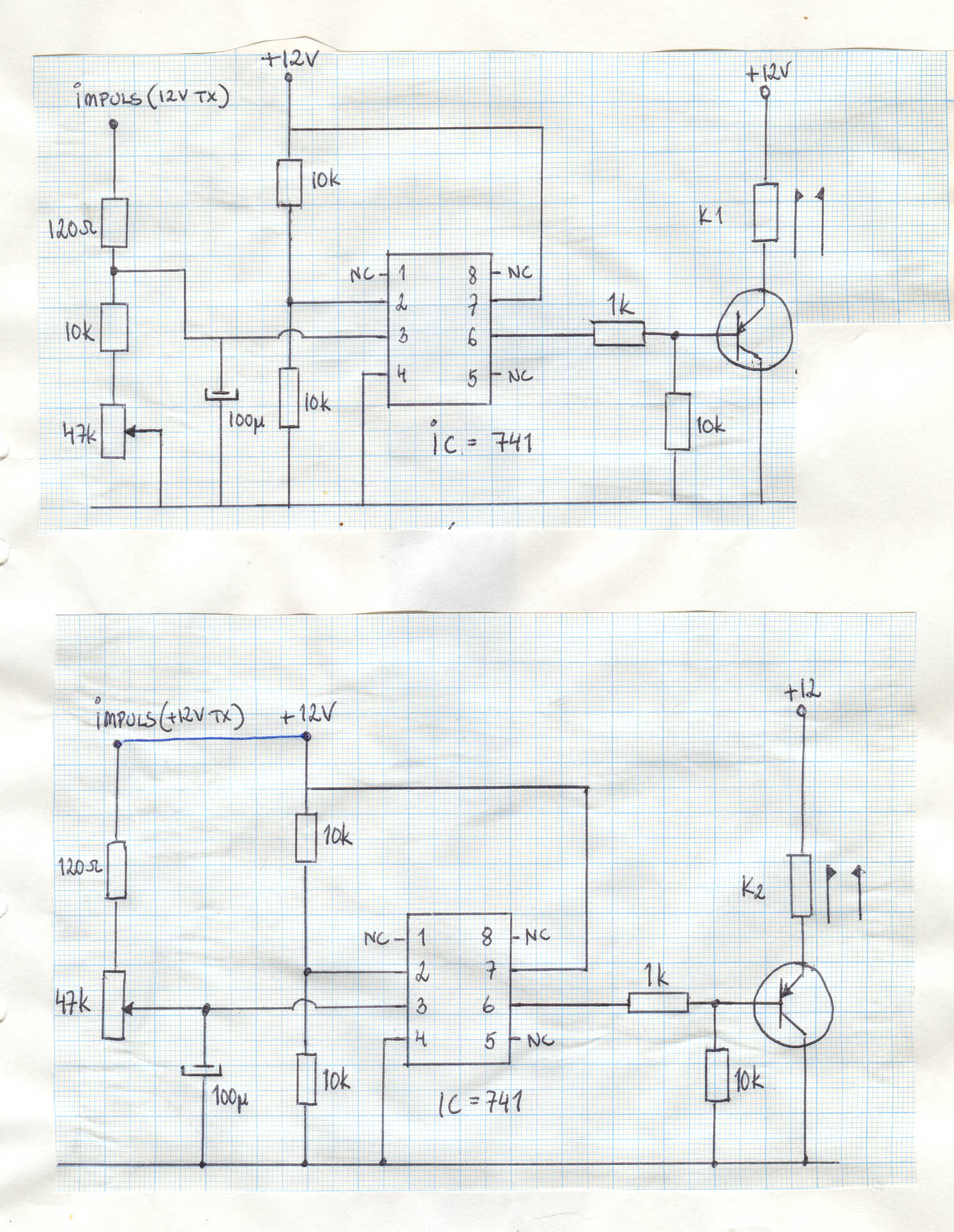
For those interested in building their own line follower robot, the tutorial provides detailed instructions on assembling the circuit, programming the microcontroller, and troubleshooting common issues. The schematic diagram included in the tutorial serves as a valuable reference for understanding the connections between the various components of the robot.Here the complete electrical circuit diagram of line follower robot which built based on ATmega16. There are three modules of line follower robot circuit that are sensor module, microcontroller module and DC motor module. Download thedocument of ATmega16 line follower robot tutorialfor complete tutorial including the working explanation of circuit
and program, source code and schematic diagram. We aim to transmit more information by carrying articles. Please send us an E-mail to wanghuali@hqew. net within 15 days if we are involved in the problems of article content, copyright or other problems. We will delete it soon. 🔗 External reference
Related Circuits
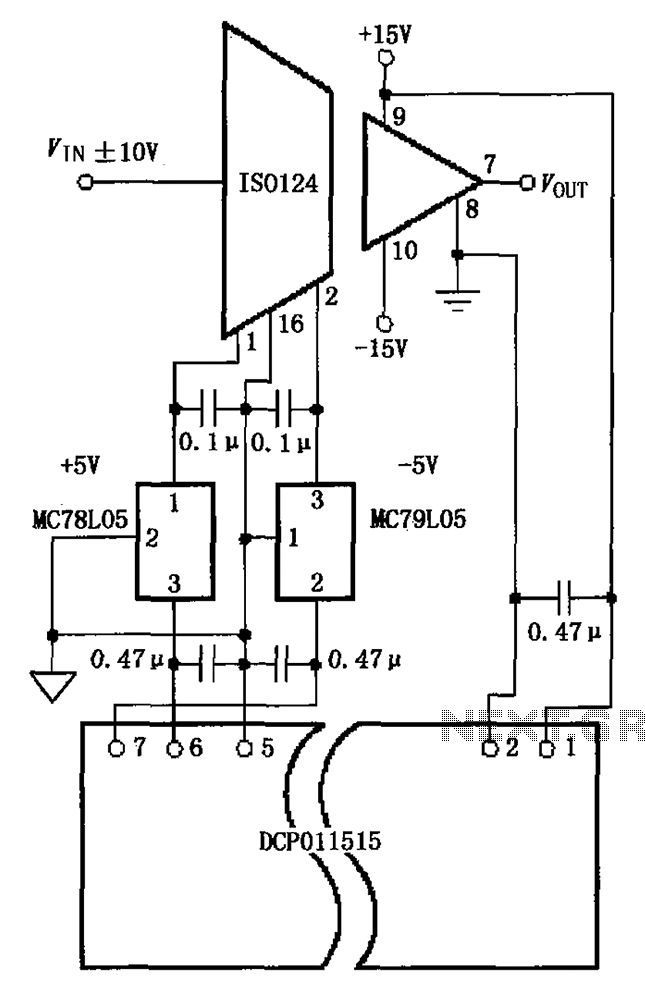
The circuit depicted in the figure includes the ISO124 and MC78L05 components, along with an external regulator, MC79L05, and the DCP011515, which collectively enhance the power supply rejection ratio (PSR) of the circuit. The input signal, VIN (maximum swing...
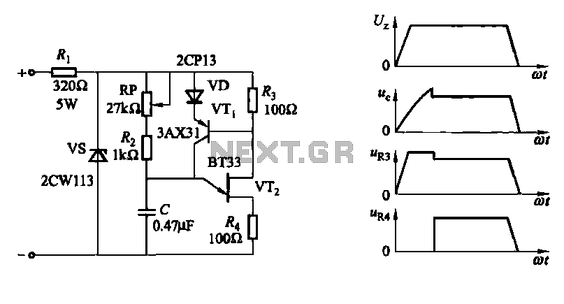
A conventional single junction transistor trigger circuit is limited to producing narrow pulses due to the rapid turn-off characteristics of the single-junction transistor. To address this limitation, a PNP transistor is added to the single-junction transistor trigger circuit, which...
Crystal 80mW FM transmitter circuit diagram of the production The Crystal 80mW FM transmitter circuit is designed to generate frequency modulated (FM) signals suitable for short-range audio transmission. This circuit primarily consists of a crystal oscillator, which serves as...
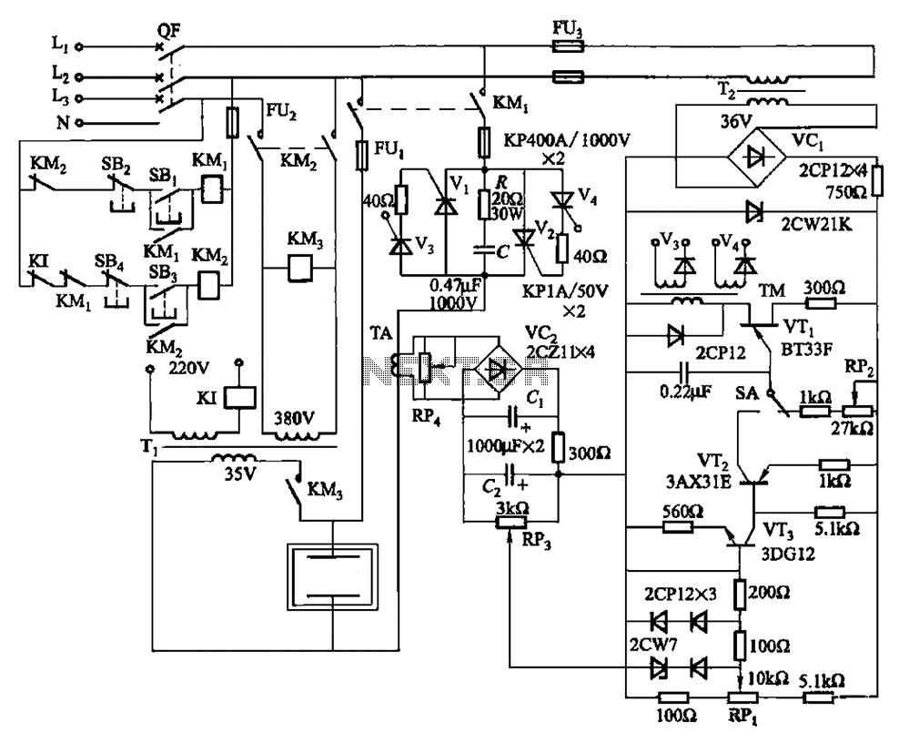
80 kW resistance salt bath furnace control circuit. The salt bath resistance furnace is a high-power device that employs fast start and temperature control technology to significantly save energy. The circuit includes a single-junction transistor (VTi) used as a...
A 12-volt power supply is used to operate a sequencer board that controls external relays for coaxial relays, a preamplifier, and an amplifier. The sequencer board features DIL relays designed to drive these external relays. Although there are more...
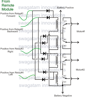
The market is filled with high-end remote-controlled toy cars; however, for hobbyists, creating one at home can be a unique experience. The following article explains how to configure a simple remote-controlled toy car using a pre-made 4-relay remote control...