
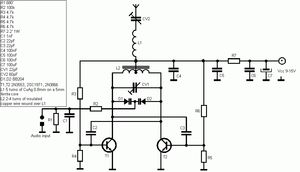
Making a circuit diagram of the crystal 80mW FM Transmitter

The Crystal 80mW FM transmitter circuit is designed to generate frequency modulated (FM) signals suitable for short-range audio transmission. This circuit primarily consists of a crystal oscillator, which serves as the frequency-generating component, and an amplification stage that boosts the output power to 80mW, allowing for effective transmission over a limited distance.
The key components of the circuit include a crystal oscillator, typically operating at a frequency of 88 to 108 MHz, which is the standard FM broadcast band. The oscillator is formed using a quartz crystal that provides stability and precision in frequency generation. The output from the oscillator is then fed into a buffer amplifier, which isolates the oscillator from the subsequent stages and prevents loading effects that could alter the frequency.
Following the buffer amplifier, a modulator stage is incorporated to allow audio signals to vary the frequency of the carrier wave. This is typically achieved using a transistor or an operational amplifier configured in a way that the audio input alters the biasing conditions, thereby modulating the frequency of the output signal.
To achieve the desired output power of 80mW, a final amplification stage is included. This could involve a class A or class C amplifier configuration, depending on the design requirements for efficiency and linearity. The final output is then coupled to an antenna, which radiates the FM signal. The choice of antenna design can significantly affect the range and quality of the transmitted signal.
Power supply considerations are also critical in this circuit. A regulated power supply is recommended to ensure stable operation of the transmitter, minimizing frequency drift and maintaining consistent output power. Additionally, bypass capacitors should be placed close to the power pins of the active components to reduce noise and enhance performance.
In summary, the Crystal 80mW FM transmitter circuit is a compact and efficient design suitable for low-power audio transmission, utilizing a crystal oscillator for frequency stability, a modulation stage for audio integration, and amplification stages to achieve the required output power. Proper design and implementation of each stage are essential for optimal performance and reliability of the transmitter.Crystal 80mW FM transmitter circuit diagram of the production
Related Circuits

When light strikes the Light Dependent Resistor (LDR), its resistance decreases significantly. The voltage at the junction of the LDR and resistor R2 gradually charges capacitor C2 through resistor R1. After approximately 10 seconds, the voltage across the capacitor...
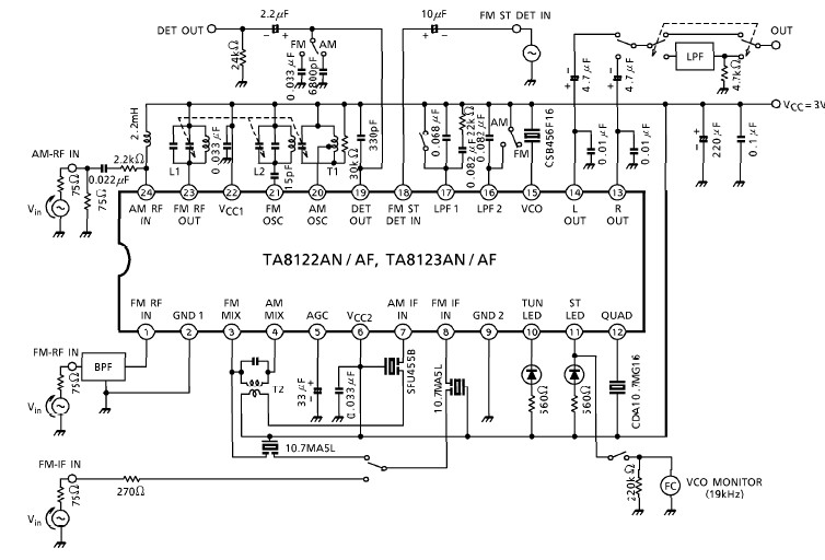
A simple low-power AM/FM radio receiver electronic project can be designed using the TA8122 integrated AM/FM receiver, manufactured by Toshiba Semiconductor. This radio receiver circuit can be utilized for portable radio applications or similar devices. The TA8122 radio receiver...
FM Broadcast Audio Transmitter. The circuit includes a frequency-modulated oscillator, an audio preamplifier with pre-emphasis to provide the frequency-modulating signal, and a buffer amplifier to drive the antenna connector. The FM radio pirate introduction to community radio electronics presents...
The circuit for automatic brightness adjustment in a television utilizes a photosensitive resistor and a contrast potentiometer connected to an intermediate stage. The photosensitive resistor varies its resistance based on light intensity, causing changes in the potential at the...
This is a compact and straightforward FM radio receiver capable of tuning into local FM stations. Its minimalistic design renders it suitable for various applications. The FM radio receiver circuit typically consists of several key components that work together to...

By adjusting one potentiometer, the output of this circuit can be varied from a positive version of the input signal, smoothly transitioning through zero output, and then to a negative version of the input. For instance, if the input...