
atmel driving LEDs directly from microcontroller pins

For example, if 10 pins are each driving an LED at 8 mA, the individual specifications may be met, but the overall current limit for the microcontroller must also be considered. The second method depicted in the original input is flawed as drawn; a resistor should be added in series with the LED to ensure the current does not exceed its rated maximum. For an LED rated at 20 mA with a forward voltage drop of 2.1V and a 9V supply, the resistor value can be calculated. With 6.9V across the resistor and considering a worst-case saturation voltage of the transistor at 0.6V, the resistor value can be determined to be approximately 345 ohms, with a standard resistor value of 360 ohms being suitable.
When the transistor is used as a switchable current sink, the supply voltage does not critically affect the operation as long as it remains above a minimum threshold. When the base of the transistor is low, the transistor is off, and the LED is off. When the base is driven high (e.g., to 3.3V), the emitter voltage will be approximately 700mV less than the base voltage. The current through the resistor can be calculated accordingly, demonstrating that the LED current can be approximated based on the transistor's gain and the current through the resistor.
Overall, this circuit design ensures that the LED operates safely within its current specifications while providing adequate brightness for signaling purposes.LED will turn on when PIO goes low - acting like GND - and current will be taken from power supply not from PIO like first method. So do I must take care of maximum current of PIO although it just act like GND not like a power supply -like method 1 -.
when I make PIO low dose it really connect to GND or something else Did youtry what an LED looks like at 8mA A modern LED may have a 20mA maximum rating, but they are extremely bright when you just want to use them as a signaling indicator. jippie Jun 2 `13 at 11:58 (1) 8mA is plenty for most LEDs unless you need to see it in full sunlight (2) the second circuit shown has no current limiting resistor - 9V will blow the LED, the transistor, or both, and flatten the battery rather fast too!
(3) the third circuit is not fundamentally different from the first. Brian Drummond Jun 2 `13 at 12:09 So do I must take care of maximum current of PIO although it just act like GND not like a power supply -like method 1 Yes, you do. The 1st and 3rd methods are equivalent in modern day microcontrollers. m. Alin Jun 2 `13 at 12:15 @yahyatawil because most microcontrollers can source AND sink the same amount of current on each GPIO.
They are functionally the same thing. Only difference is your code, where turning on the led is setting the pin high (when it is the source) or low (when it acts like the ground). Passerby Jun 2 `13 at 19:13 The first and third methods you show are fine, assuming the resistor is sized so that the 8 mA maximum port pin current is not exceeded.
The difference between these two methods is whether the low or high side drive transistor in the processor is in series with the LED. Sometimes the low side transistors are a little more beefy, which is why you see method three more than method 1.
However, either method is fine as long as you take care to not exceed the current spec for the pin. Also note that some processors have a total current spec that must not be exceeded. For example, you could have 10 pins each driving a LED at 8 mA, which would be fine individually for each pin. However, if the overall processor spec is that all I/O pins together can`t source our sink more than 50 mA, for example, then you`re still out of spec.
Your method two is wrong as drawn. It will likely damage the LED or transistor. To fix it, add a resistor in series with the LED so that the LED current does not exceed its maximum rated value. For example, let`s say the LED is rated for 20 mA max, and it drops 2. 1 V in that case. With a 9 V supply, that leaves 6. 9 V accross the resistor and the transistor. The saturation voltage of the transistor is probably around 200 mV, but for worst case analisys let`s just say it`s 0.
6. 9 V / 20 mA = 345 ©, so the next size up common value of 360 © would be fine. Working backwards, and this time assuming the 200 mV drop on Q1, the LED current will be 6. 7 V / 360 © = 18. 6 mA. Even in a side by side comparison, it will be difficult for humans to distinguish that from the brightness achieved by 20 mA thru the LED. This uses the transistor as a switchable current sink, so the exact power voltage (9 V in your case) doesn`t matter over a wide range.
When the base is 0, the transistor is off and the LED is off. When the base is driven to 3. 3 V by the digital output, the emitter will be about 700 mV less, or 2. 6 V in this example. The current thru R1 will therefore be 2. 6 V / 150 © = 17. 3 mA. Since most of this current comes from the collector due to the gain of the transistor, that will be the LED current to a reasonable approximation. Note that the 9 V supply voltage didn`t enter into the calculations. As long as it is above a minimum value, the transistor will sink very nearly the same current because the transistor gain changes little with collector voltage.
If we give the transistor about 700 mV C-E voltage so that it is nicely in its linear region, then the supply must be 🔗 External reference
Related Circuits

The Atmega8 microcontroller from Atmel features numerous digital and analog input/output lines, making it an ideal choice for developing various measurement equipment. It is essential to have the GCC AVR programming environment installed, as outlined in the article "Programming...
The Atmel AT89C2051 keylogger circuit connects to a PC keyboard via a PS/2 connection cable, facilitating data transfer between the keyboard and the circuit during program execution. The Atmel AT89C2051 microcontroller is a popular choice for implementing keylogger circuits due...
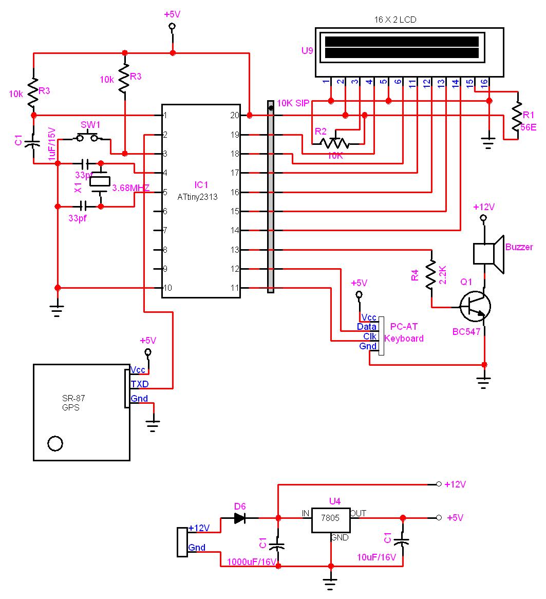
In this project, a GPS module is interfaced with an AVR microcontroller. The ATtiny2313 retrieves location data from the GPS and displays it on an LCD screen. The project involves the integration of a GPS module with the ATtiny2313 microcontroller,...
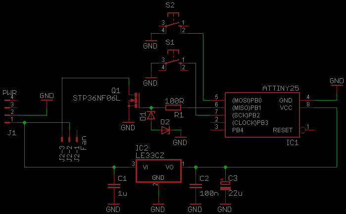
This document serves as a continuation of the previous work on PWM controllers utilizing 555 timers. The new design incorporates microcontrollers and MOSFETs in place of the 555 integrated circuits and transistors. Two versions have been developed: one equipped...
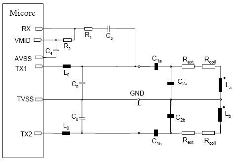
This document provides guidance on designing an antenna for the MICORE contactless reader IC family, which includes the MF RC500, MF RC530, MF RC531, SL RC 400, and CL RC 632. The antenna design and matching process is consistent...
The following are current regulator circuits that can be used to drive light emitting diodes. As always, take time to do some testing before attempting to use these circuits in actual applications. Current regulator circuits are essential for controlling the...