
Audible Logic Probe

The NE556 timer is a dual timer IC that can operate in various configurations, including monostable and astable modes. In the context of an audible logic probe, it is primarily used in a monostable configuration to generate a sound signal when a specific logic level is detected at the terminal under test.
To implement this circuit, the NE556 is connected to a speaker or piezo buzzer, which will produce sound when a high or low logic level is sensed. The circuit can include a resistor and capacitor connected to the trigger pin of the NE556 to define the output pulse width, allowing the user to adjust the duration of the sound produced.
The input terminal of the probe is connected to the logic circuit being tested. When the terminal is at a high logic state (typically close to the supply voltage), the NE556 is triggered, causing the output to go high and activating the buzzer. Conversely, when the terminal is at a low logic state (ground level), the output remains low, and the buzzer remains silent.
Additional components such as diodes can be included to protect the circuit from voltage spikes, and a potentiometer may be added to allow for volume control of the audible output. This circuit provides a practical solution for testing digital logic states without the need for visual indicators, making it a valuable tool for engineers and technicians in the field of electronics.We can use NE556 timer IC to make indication of static of terminal in digital logic audible.? Audible logic probe can be very useful when we have to visually. 🔗 External reference
Related Circuits
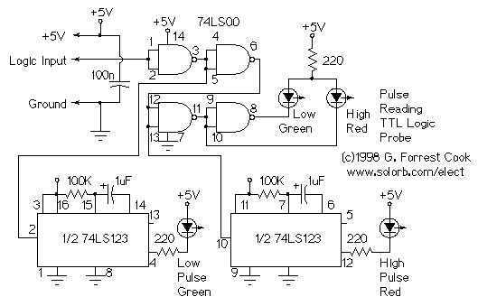
This circuit uses LEDs to display logic states for high, low, rising pulse, and falling pulse. It is generally useful for debugging logic circuitry. The described circuit employs light-emitting diodes (LEDs) as visual indicators for various logic states in digital...

The logic diagram of the CD4538BC Dual Precision Monostable is shown in the following schematic diagram. This IC is a dual, precision monostable multivibrator with independent trigger and controls, according to the datasheet. This CD4538BC IC features a wide...
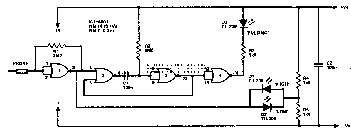
The logic probe can indicate four input states, as follows: floating input - all LEDs off; logic 0 input - D2 switched on (D3 will briefly flash on); logic 1 input - D1 switched on; pulsing input - D3...
This precise one-pulse-per-second clock is constructed using a few common components and is driven by a 50 or 60 Hertz mains supply without a direct connection to it. An audible beep or a metronome-like click, along with a visible...
Working on live telephone circuits can be a problem. You just can't connect a normal scope probe to the circuit while it is tied to the phone line. Neither side of a phone line is ground. When a phone...
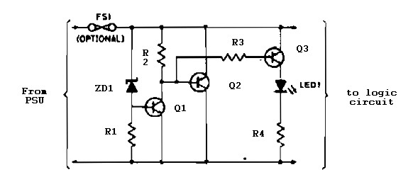
Logic overvoltage protection power supply. Refer to the designated page for an explanation of the power supply circuit diagram mentioned above. The logic overvoltage protection power supply is designed to safeguard sensitive electronic components from voltage spikes that could potentially...