
Pulse Reading Logic Probe

The described circuit employs light-emitting diodes (LEDs) as visual indicators for various logic states in digital electronics. The primary function is to provide real-time feedback on the status of digital signals, which is essential for debugging and testing logic circuits.
The circuit typically consists of several input lines connected to the logic signals being monitored. Each input line is associated with an LED, which illuminates based on the logic state of the signal it represents. For instance, a high logic level (often represented by a voltage close to the supply voltage) will turn on the corresponding LED, while a low logic level (close to ground) will turn it off.
To detect rising and falling pulses, the circuit can include additional components such as flip-flops or comparators. These components can latch the state of the input signal, allowing the circuit to differentiate between transitions. For example, when a rising edge is detected, a specific LED may light up momentarily to indicate that a transition from low to high has occurred. Conversely, a falling edge can trigger another LED to indicate the transition from high to low.
Power supply considerations are crucial; the circuit is typically powered by a regulated DC voltage source, ensuring that the LEDs operate within their specified forward voltage range. Current-limiting resistors are also necessary in series with each LED to prevent excess current that could lead to LED failure.
For practical implementation, the circuit can be built on a breadboard for prototyping or designed on a printed circuit board (PCB) for more permanent applications. Additionally, the layout should minimize interference from adjacent signals to avoid false triggering of the LEDs.
This LED display circuit can be invaluable in educational settings, allowing students and engineers to visualize logic states easily, thus enhancing understanding and troubleshooting capabilities in digital electronics.This circuit uses LEDs to display logic states for high, low, rising pulse, and falling pulse, it is generally useful for debugging logic circuitry. 🔗 External reference
Related Circuits
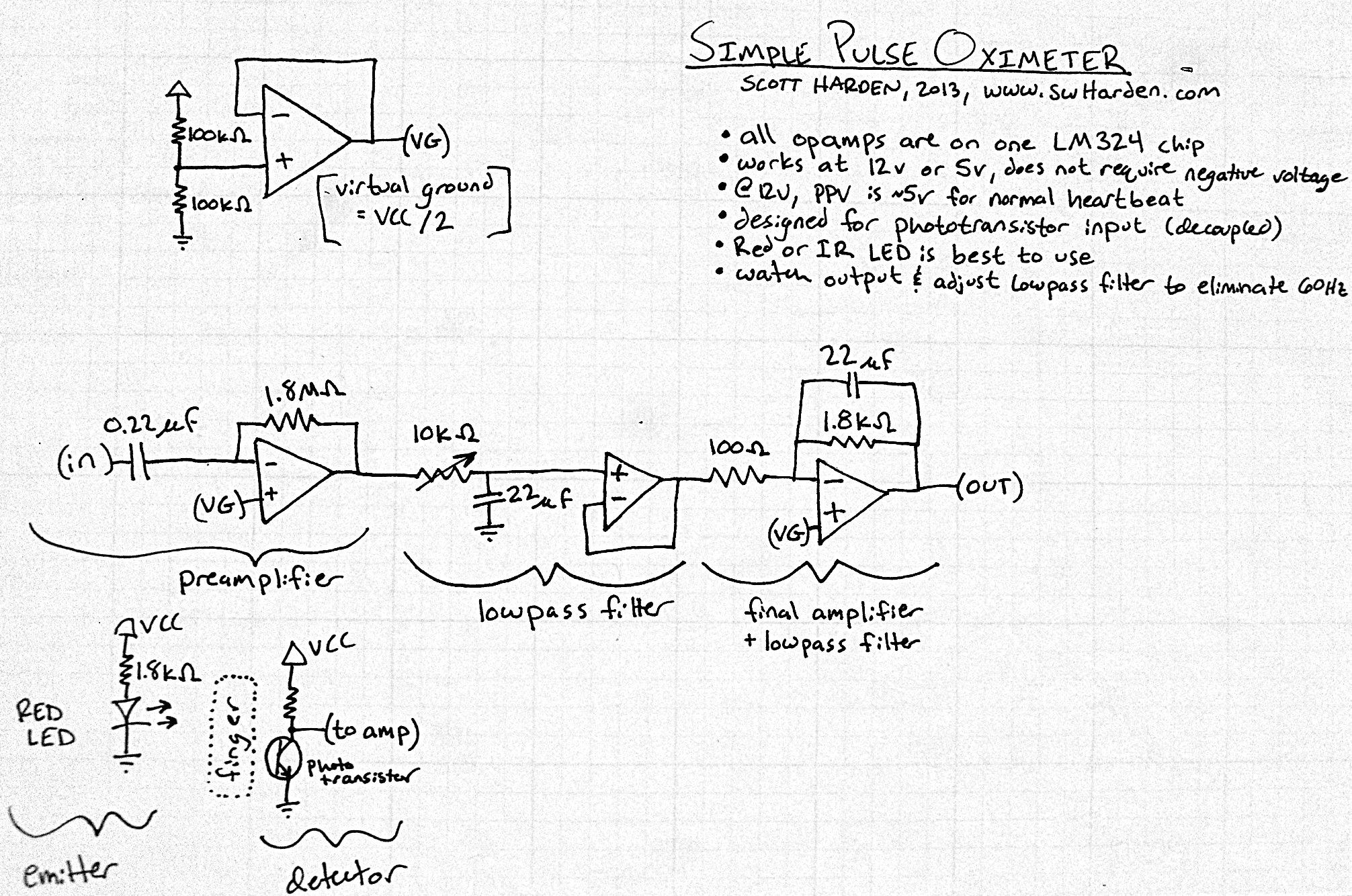
The input capacitor for the phototransistor at the bottom is responsible for feeding the operational amplifier (op-amp). However, the output from the phototransistor consistently remains between ground (GND) and the supply voltage (Vcc). The necessity for an input capacitor...
This section provides details for generating a composite video output signal from a camera to drive an external monitor. The circuit, designed by Peter Smith, integrates a DC-restorer, a switchable gamma corrector, and a video/sync mixer using a photodiode...
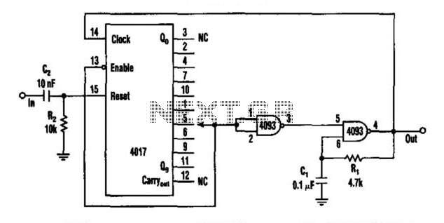
This circuit features a rate multiplier utilizing a 4093 Schmitt trigger configured as an oscillator, which drives a 4017 decade counter. When a pulse is present at the input (to C2), the 4017 is reset, causing output zero to...
This circuit is utilized in a multiplier that operates with one of the operational amplifiers in an analog computer. The double-triode V1 in this configuration provides pulse-amplitude modulation, which is intended for use with a separate pulse-width modulator to...
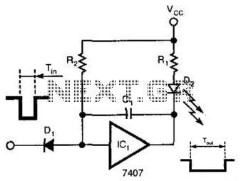
A single gate (open collector, non-inverting) generates a simple one-shot pulse that lasts for a duration equal to t, plus the RiCi time constant. R2 serves as a pull-up resistor to maintain the input of the gate high while...
This simple circuit generates narrow pulses at a frequency of approximately 700-800 Hz. The pulses, which contain harmonics extending into the MHz range, can be injected into audio or radio-frequency stages of amplifiers and receivers for testing purposes. A...