
Audio Alarm Circuit

The circuit operates as an audio level detector and alarm system, utilizing a combination of amplification, rectification, and signal processing to monitor ambient sound levels. The condenser microphone (U1) is the primary sensing element, converting acoustic signals into electrical signals. The output from U1 is conditioned by resistors R1, R2, and R3, which manage current flow and set the output voltage range, ensuring compatibility with single-ended power supplies. The rectification process performed by diodes D1 and D2 transforms the AC signal into a pulsating DC signal, which is then smoothed out by capacitor C3, providing a stable DC voltage that reflects the ambient sound level.
The operational amplifier U2 is configured in a comparator mode, comparing the processed voltage from the microphone with a reference voltage established by R11. The reference voltage can be adjusted to set a threshold for sound detection. When the ambient noise level exceeds this threshold, the output of U2 shifts from low to high, indicating that a significant sound event has occurred.
Transistor Q1 serves as a switch, initially biased into a partially on state by the low output from U2, while the voltage divider formed by R8 and R10 ensures that Q2 remains off during low noise conditions. Upon detection of elevated noise levels, Q1 is fully turned on, which in turn activates Q2. This action drives the piezo buzzer to emit sound, alerting users to the detected noise.
Overall, this circuit effectively combines audio sensing, signal processing, and alarm activation in a compact design, suitable for applications such as noise monitoring systems, alarms, and other sound-activated devices. In the circuit, U1 amplifies the audio picked up by the condenser microphone. Resistor Rl limits current, while R2 and R3 center the output of the amplifier to %B+ to allow a single-ended supply to be used. Diodes D1 and D2 rectify the output of Ul, and C3 filters the resulting pulsing dc. Thus, a dc voltage that is proportional to the ambient sound level is produced.That voltage is presented to the noninverting input of U2.
The inverting input is provided with a reference voltage of between 0 and lAB+, which is set by Rll.As long as the noise level is low enough to keep the voltage at pin 3 lower than the voltage at pin 2, the output of U2 stays low (approximately 1 V). That is enough to bias Ql partially on. A voltage divider, formed by R8/R10 and Ql (when it`s partially on), prevents Q2 from turning on.When the noise level is high enough to bring the voltage at pin 3 higher than the voltage at pin 2, the output of U2 goes high. That turns Ql fully on and drives Q2 into saturation. The piezo buzzer then sounds until the power is cut off.
Related Circuits
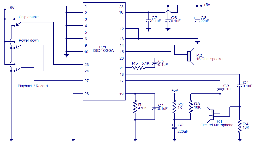
This circuit is designed in response to a request made by Mr. Vignesh for a voice recording and playback system. The circuit utilizes the ISD1020A IC from ISD, which is a CMOS single-chip record/playback device capable of recording voice...
This solid-state Tesla Coil design is similar to the two-transistor version available on this site, utilizing a standard flyback transformer to generate high voltage output. Unlike the previous design, it employs a 555 timer to effectively drive a single...
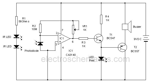
This circuit utilizes invisible infrared light to detect the movement of individuals through a doorway. A brief beep will be emitted when the infrared beam is interrupted. The infrared movement detection circuit employs an infrared LED and a photodiode or...
The sound system features a de-sensitized design with a maximum range that can be increased if desired. It includes two tone controls: one offering a lift of 10 dB and the other providing a subtle cut of 3 dB....
This 300W RF power amplifier for an FM transmitter utilizes 2 x TP9383 transistors. It operates within the 88 - 108 MHz frequency band. The 300W RF power amplifier is designed specifically for FM transmission applications, providing high power output...

The ongoing debate regarding the superiority of valves versus transistors is not the focus here. However, for those undecided, this simple amplifier serves as an excellent test. It employs a valve as a pre-amplifier and a MOSFET in the...