
Voice recorder/playback circuit

The circuit design for the ISD1020A voice recording and playback system incorporates several critical components and configurations that enhance its functionality and performance. The ISD1020A chip serves as the core of the system, providing the necessary features for audio capture and playback. The automatic gain control (AGC) feature is essential for maintaining consistent audio levels, compensating for variations in input signal strength. The resistor R1 and capacitor C1 form an RC time constant that controls the AGC release time, ensuring smooth transitions in audio levels during playback.
The anti-aliasing filter integrated within the IC helps to prevent distortion during the recording process, allowing for clearer audio reproduction. The built-in audio amplifier boosts the recorded signal, making it suitable for playback through various output devices. The smoothing filter further refines the audio output, enhancing the overall listening experience.
The circuit's design adheres to the application diagram provided in the ISD1020A datasheet, ensuring proper connections and functionality. The chip enable pin (CE) is crucial for activating the device; keeping it low allows the chip to enter record or playback modes. The playback/record pin (P/R) plays a vital role in determining the operational state of the chip. The use of switch S3 facilitates easy toggling between recording and playback modes, providing user-friendly operation.
The power-down pin (PD) is an essential feature that allows for energy conservation when the device is not in use. By holding this pin high with switch S2, the circuit enters a low-power state, significantly extending battery life in portable applications.
Additionally, the configuration of resistor R5 and capacitor C5 across pins 20 and 21 introduces a low-frequency cut-off, preventing unwanted low-frequency noise from affecting the clarity of the recorded voice. This ensures that the audio output remains within the desired frequency range, enhancing the overall quality of the playback.
In summary, this circuit effectively combines the capabilities of the ISD1020A with thoughtful design choices to create a reliable and efficient voice recording and playback system suitable for various applications.This circuit is designed in response to a request made by Mr Vignesh. What he requested was a circuit for recording and playing voice. I think this circuit is enough for the purpose. This circuit is based on the IC ISD1020A from ISD. The ISD1020A is a CMOS single chip record/playback device. The chip can record voice for 20seconds and has many fea tures like automatic gain control, anti aliasing filter, built in audio amplifier and smoothing filter. The IC is fully compatible to microprocessors and can be used for a myriad of applications. The voice is stored in their natural form in the non-volatile memory cells inside the IC which enables a high quality reproduction.
The recorder voice can be retained in the chip for as long as 100 years and the chip is capable to have a 100000 read/write cycles. The circuit is designed as per the application diagram in the datasheet. Pin23(CE) is the chip enable pin and it has to be held low using switch S1 in order to perform a record or playback cycle.
Pin 27 (P/R) is the playback/record pin and a high level on it selects a playback cycle while a low level on it selects a record cycle. The selection can be done using the switch S3. The pin 24 (PD) is the power down pin. It has to be held high using switch S2 in order to pull the device to a extremely low power mode while there is no recording or playback (idle state).
The resistor R1 and capacitor C1 determines the release time of the internal AGC circuit. The resistor R5 and capacitor C5 connected across the pin 20 and pin 21 provides an additional cut-off to the low frequency end of the voice pass band. 🔗 External reference
Related Circuits
The DTMF infrared remote control circuit utilizes a DTMF encoded signal that can be decoded by a specialized decoder and the PLL audio decoder LM567. However, a DTMF encoded signal decoded by a single decoder yields only one frequency....
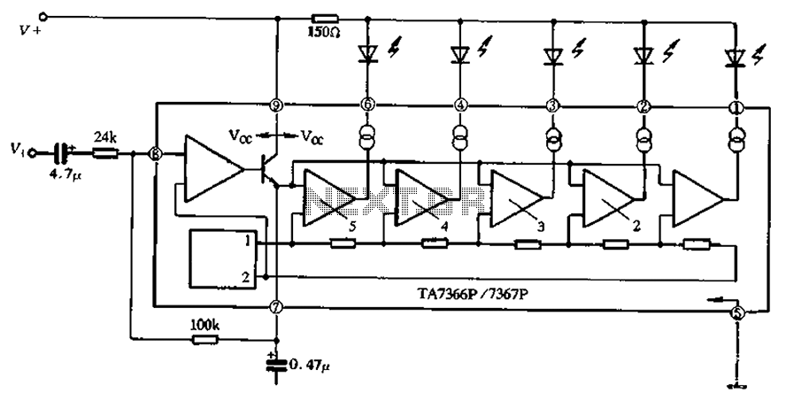
The TA 7366/7367 is a commonly used single display driver circuit manufactured by Toshiba Corporation. It features a 5 LED driver circuit and is designed in a 9-pin single in-line plastic structure. The circuit configuration includes an operational amplifier...
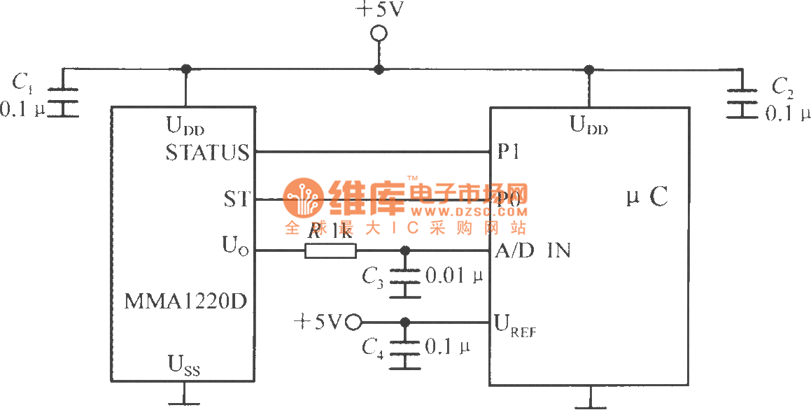
The microcontroller within the A/D converter can utilize a PIC MCU produced by Microchip. The MMA1220D's state and self-test pins are connected to the P1 and P0 ports of the microcontroller, with its output voltage sent to the input...
This type of design can produce a very high amperage current for a fraction of a second that can be used to do some useful work if properly harnessed. A point to remember is that Paul Baumann built his...
The circuit consists of two 555 timer oscillators configured in a dual timer arrangement, both set up in astable mode. Components include a 1N4148 diode and a 555 integrated circuit. The dual 555 timer circuit operates in astable mode, generating...
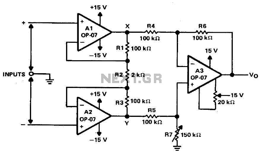
Operational amplifiers A1 and A2 are connected in a non-inverting configuration to form amplifier A3. The operational amplifier A3 can be classified as a subtractor circuit that converts the differential signal between the floating points X and Y into...