
audio amp

This circuit assembly involves several key components that must be installed correctly to ensure proper functionality. The red LED, designated as D2, should be oriented such that its flat side aligns with the outline marked on the printed circuit board (PCB). This alignment is crucial as it ensures that the LED is correctly polarized; improper installation could lead to LED failure.
Next, a jumper wire must be placed at the location marked R4. This jumper serves to bypass a resistor or connect two points on the PCB, depending on the design requirements. The specific purpose of this jumper should be verified against the schematic to maintain circuit integrity.
The installation of a 220µF electrolytic capacitor at C8 is also required. It is essential to connect the negative terminal of the capacitor to the ground to prevent reverse polarity, which can damage the capacitor and affect circuit performance. The capacitor plays a vital role in filtering and stabilizing the voltage within the circuit, thereby ensuring that the connected components operate effectively.
Finally, pin 2 of connector J4 must be connected to the Automatic Gain Control (AGC) input on the 612 HF mixer. This connection is critical for managing the gain of the mixer, allowing it to adjust the amplification level based on the input signal strength. Properly establishing this connection ensures that the mixer can perform optimally in various signal conditions.
Overall, attention to detail during the assembly of this circuit is paramount to ensure that all components function correctly and that the circuit performs as intended.Install the red LED at D2. Align the flat side of the LED with the PCB outline. Install a jumper wire at R4 and install a 220uF electrolytic cap at C8 with the negative side to ground. Connect pin2 of J4 to the AGC input on the 612 HF mixer. 🔗 External reference
Related Circuits
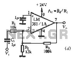
National Semiconductor (NS Company) produces audio integrated circuits (ICs) that offer wide frequency response and low noise. These circuits provide excellent performance across all NS products. The circuit illustrated in Figure 3-12 includes a preamplifier and a singing equalizer...
The foundation of this amplifier is detailed in Project 03, which does not claim to be cutting-edge; the base design is over 20 years old. It is straightforward to assemble, utilizes readily available components, and is stable and dependable....
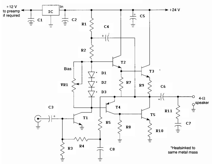
A 10 Watt audio amplifier circuit diagram is presented. This circuit serves as a general-purpose 10-W power audio amplifier, suitable for medium power applications or for use in modulation within AM transmitters. To achieve higher power levels, up to...
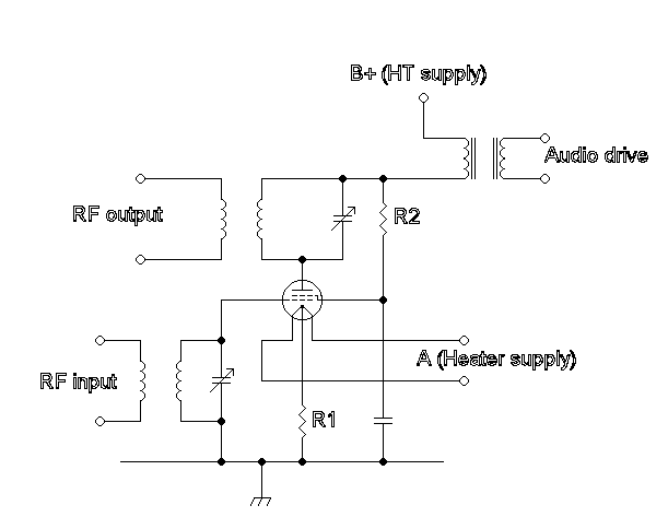
Amplitude modulation (AM) is a technique used in electronic communication, primarily for transmitting information via a radio carrier wave. AM operates by varying the strength of the transmitted signal in relation to the information being conveyed. For instance, changes...
The purpose of this circuit is to automatically turn off any device plugged into its power outlets after a certain period of time. Shutoff is activated by an absence of an audio signal or by a standard timer function....
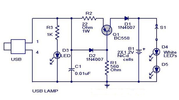
A simple USB-powered lamp designed to illuminate a desktop during power outages. The circuit operates at 5 volts sourced from a USB port. The 5V from the USB is directed through a current-limiting resistor (R2) and a transistor (Q1)....