
10 Watt Audio Amplifier

The 10 Watt audio amplifier circuit typically consists of a few key components: a power supply, transistors, resistors, capacitors, and possibly a heat sink for thermal management. The power supply provides the necessary voltage and current to drive the amplifier. The transistors, which can be configured in a push-pull arrangement, serve as the main amplifying elements, allowing the circuit to boost the audio signal's power level effectively.
Resistors in the circuit are used to set the biasing conditions for the transistors, ensuring they operate in the appropriate region of their characteristics for linear amplification. The bias resistor value is crucial, as it directly influences the circuit's performance and maximum output power. By adjusting this resistor, one can optimize the amplifier for different applications, whether for standard audio amplification or for modulation in AM transmission.
Capacitors are employed for coupling and decoupling purposes, ensuring that AC signals pass through while blocking DC components that could affect performance. Additionally, capacitors help in stabilizing the power supply, filtering out noise that could distort the audio signal.
For applications requiring higher power output, the circuit can be modified by increasing the supply voltage. However, care must be taken to ensure that the transistors can handle the increased voltage and current without overheating or becoming damaged. This is where the selection of a suitable heat sink becomes important, as it dissipates heat generated during operation, maintaining the reliability and longevity of the amplifier.
In summary, the 10 Watt audio amplifier circuit is a versatile design that can be adapted for various applications, including audio amplification and AM modulation. By understanding the relationships between the components and their configurations, one can effectively tailor the circuit to meet specific power requirements while ensuring optimal performance.10 Watt Audio Amplifier circuit diagram. This is general purpose 10-W power audio amplifier circuit for medium power amplifier or use a modulation in the AM transmitter. For higher power up to 30 W can be obtained by increasing the voltage and change the bias resistor value.
🔗 External reference
Related Circuits
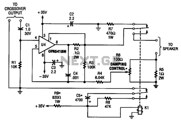
Designed to power a low-frequency subwoofer speaker system, the amplifier can deliver up to 100 W into an 8-ohm load. The OPA541BM operational amplifier, produced by Burr-Brown Corporation, necessitates heatsinking for optimal performance. Additionally, the design incorporates a damping...

A very high-power amplifier with 10 pairs of power transistors. It can utilize MJ15024 and MJ15025 or MJ21193 and MJ21194. These 20 transistors function as the final active components. The design is based on four integrated circuits: TL072, TL074,...
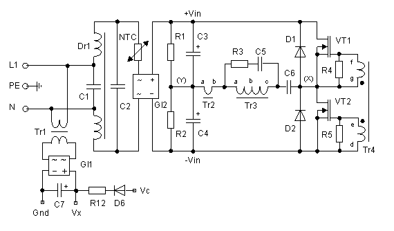
Up to 10 A continuous output current, or operation with 50 % ESD and 18 A peak current are possible without a fan if sufficient natural air flow is present and the ambient temperature does not exceed 30 °C....
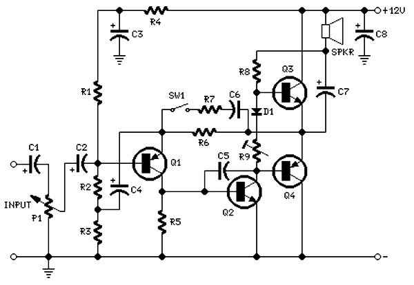
The circuit is intentionally designed using older type transistors to achieve harmonic distortion and to mitigate the challenges of sourcing high-quality components. The amplifiers can be easily powered by a plug-in wall transformer rated at 12V. When SW1 is...

Proper grounding is essential for eliminating hum and ground loops. The ground connections for J1, P1, C2, C3, and C4 should all be connected to the same point. Additionally, connect C9 to the output ground. In electronic circuits, grounding serves...
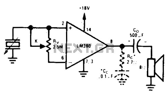
Used when maximum input impedance is required or when the signal attenuation of the voltage divider volume control is undesirable. In electronic circuit design, achieving maximum input impedance is often critical, particularly in applications involving sensitive signal processing. The use...