
audio Can I use a PNP Transistor with an Electret Microphone to get an non-inverting output for my Arduino

An electret microphone circuit typically consists of the microphone itself, a bias resistor (R1), a coupling capacitor (C1), and a transistor for amplification. In this case, a PNP transistor can be employed to achieve the desired non-inverting output. The electret microphone generates an AC signal superimposed on a DC bias. The bias resistor (R1) provides the necessary voltage for the microphone's operation, allowing it to produce an AC signal that varies with sound pressure levels.
To achieve a non-inverted output, the following configuration is recommended: The electret microphone connects to the base of a PNP transistor through a coupling capacitor (C1). The emitter of the PNP transistor is connected to the positive supply voltage (e.g., +5V), while the collector is connected to the output node. A load resistor (R2) is connected from the collector to ground. This configuration allows the output voltage to rise as the sound level increases, providing the desired linear response where 0V corresponds to silence and 5V corresponds to maximum sound levels.
The coupling capacitor (C1) blocks the DC component from the microphone signal, allowing only the AC component to pass to the base of the PNP transistor. The transistor amplifies this AC signal while maintaining the non-inverted characteristic. The output voltage can be read directly by an analog-to-digital converter (ADC), which will interpret the varying levels between 0V and 5V.
For optimal performance, it is essential to select appropriate values for the resistor (R2) and the coupling capacitor (C1) to ensure that the frequency response of the circuit accommodates the desired sound frequencies. Additionally, a bypass capacitor may be added across the power supply to filter out any noise that could affect the microphone's performance.
In summary, the proposed circuit configuration allows for the generation of a non-inverted output signal from an electret microphone using a PNP transistor, enabling the detection of varying sound levels in a linear manner suitable for ADC input.Read the generic sound level from an Electret Microphone. I`ve seen a number of schematics with NPN transistors, that will provide an inverted output (~5V when quiet, ~0V when loud, linear operation in between). However, I would like non-inverted output (linear operation, super quiet input gives ~0V, super loud input gives ~5V).
I realize I could easily correct for this in software, but it just seems backward to me in a way and I cannot find any examples of a non-inverting output with a PNP transistor. Is there a reason for this beyond being uncommon If it`s possible, could anyone provide a schematic of an electret microphone and PNP transistor that will give ~0V when quiet and ~5V when loud It seems I was rather confused in what I would get as output from the NPN preamp, which would be 0V for silence, and +/- Vin / 2. Here`s what I want instead: 0V when silent, ~2. 5V in medium sound levels, ~5V in maximum sound levels. This could be read by the ADC easily into `sound level` without much work at all. However, I cannot feed voltages < 0V or > 5V to the analog comparator. It looks like I want the above with an envelope detector, however that would only get me from 0V to 2.
5V. How do I make it vary the full 0V to 5V, 0V being `quiet` and 5V being `loud`, with everything in between linear Unfortunately, this circuit will not generate a DC voltage, if the output is taken on the right side of C2. It will generate an AC voltage. This is because of the capacitors. Capacitors do not allow DC voltages pass through them. abdullah kahraman Feb 11 `13 at 12:15 The Arduino has 6 analog inputs, which read 0-1023 for 0V-5V. AC is what I`d be looking for there, right Perhaps I`d need a diode to not be passing negative voltage to the Analog comparator Ehryk Feb 11 `13 at 12:20 Yes, but a diode will drop 0.
6V on itself. Maybe you should try to make the supply voltage 5V. The supply voltage is the one labeled "+3 to 9 Volts". Then remove C2. Then, read the analog value on the collector of Q1. Experiment with different sound levels, for example clap, talk, shout, be quiet, whisper, and see the analog reading changing. However, it will be a sine wave added with a DC value. abdullah kahraman Feb 11 `13 at 12:24 Reading your question and comments it appears that your questiojn is not clearly stating what you want.
It seems that you want an AC level which diminishes in magnitude as the input voltage increases. If this is the case you need to state it clearly. If this is not the case, can you please explain "I`m not looking for a logic 0-1, the Arduino`s analog inputs have a 10-bit ADC that gives 0-1023 for 0V-5V, respectively" in this context. |. Russell McMahon Feb 11 `13 at 13:06. IF you are talking about DC levels the question is still unclear. An AC signal will be centred on the DC bias point. This is relatively fixed with signal strength. Can you very clearly and in simple terms explain EXACTLY what you want the output to do as the input signmal goes from 0VAC to Max Vin AC.
Russell McMahon Feb 11 `13 at 13:07 As far as I understood, you are trying to make some kind of a sound level detector, which will let you detect if there is a sound with a certain volume or not. You can do this with minor changes to the schematic you have. But before that, you should understand the circuit. R1 is for supplying power that is needed by the microphone and this is called biasing the microphone.
A microphone generates an AC voltage, which is sometimes negative and sometimes positive and it changes most of the time. Think of a sine wave. But remember, we had some biasing to it which is a DC voltage. We have to take that out and give only the AC voltage to the amplifier. And doing this is easy with a simple, single capacitor. A capacitor does not let the DC to pass, but lets AC pass easily. We have blocked the DC portion of the voltage on the electret microphone. In this config 🔗 External reference
Related Circuits
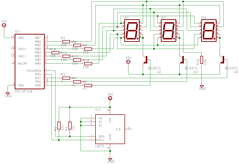
This is a test project assembled quickly on a solderless breadboard. It utilizes an LM75 temperature sensor to read the current temperature through the I2C communication protocol and displays the result. The project employs the LM75, a digital temperature sensor...
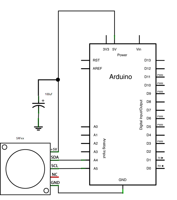
This example demonstrates how to read a Devantech SRFxx, an ultrasonic range finder that communicates via the I2C synchronous serial protocol, using Arduino's Wire Library. The I2C protocol utilizes two wires for data transmission: a serial clock pin (SCL)...
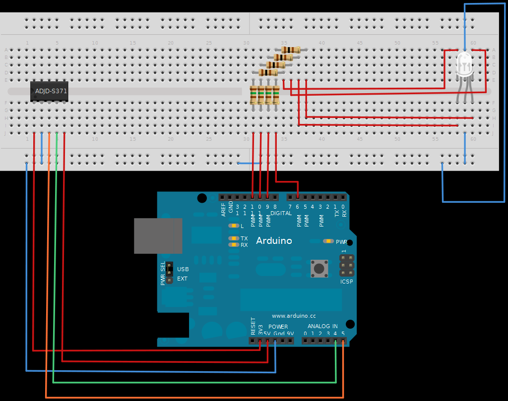
The next board presented is the ADJD-S371 Color Light Sensor Evaluation Board from SparkFun. This board emits light and analyzes the reflected color spectrum. It can be controlled via I2C, while the sleep and xclk pins were not utilized...
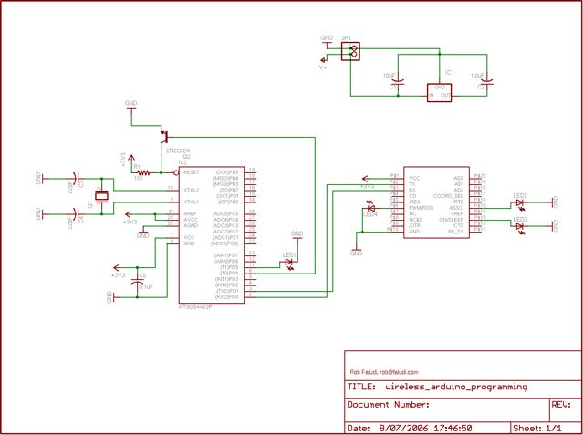
The Arduino system provides a straightforward and open-source approach for programming microcontrollers. Typically, this involves using a serial or USB cable directly connected to the microcontroller project. However, challenges arise when the project is located in inaccessible areas, such...
The LM3915 is a monolithic integrated circuit that senses analog voltage levels and drives ten LEDs providing a logarithmic 3 dB/step analog display. LED current drive is regulated and programmable, eliminating the need for current limiting resistors. More: This...
With this circuit mounted in or near every phone in the house, it will allow users to know if the phone is being used and not to pick up the phone. When a phone is taken off hook, the...