
lm75 temperature sensor with 7 segment display output

The project employs the LM75, a digital temperature sensor with I2C interface, which allows for easy integration with microcontrollers. The LM75 operates within a temperature range of -55°C to +125°C and provides a 9 to 12-bit temperature resolution. The sensor communicates with a microcontroller, such as an Arduino or Raspberry Pi, over the I2C bus, which simplifies wiring and allows for multiple devices to share the same communication lines.
In the schematic, the LM75 is connected to the microcontroller via two wires: the Serial Data Line (SDA) and the Serial Clock Line (SCL). Pull-up resistors are typically included on these lines to ensure proper signal levels. The microcontroller is programmed to initiate communication with the LM75, request temperature data, and process the received digital value to convert it into a readable temperature format.
The display component of the project could be an LCD or OLED screen, which is driven by the microcontroller. The microcontroller processes the temperature data obtained from the LM75 and formats it for output on the display. The display is connected to the microcontroller using appropriate data and control lines, depending on the display technology used.
Power supply considerations should also be addressed, ensuring that both the LM75 and the microcontroller receive the appropriate voltage levels, typically 3.3V or 5V, depending on the specific components used in the project.
Overall, this project serves as a fundamental demonstration of using a digital temperature sensor with I2C communication, showcasing the integration of sensors and displays in electronic circuit design.This is a test project built hastily on a solder less breadboard. It uses a LM75 to read the current temperature via I2C and displays the result.. 🔗 External reference
Related Circuits

This is a water sensor circuit design based on a Conductive Liquid Level Sensor. This single-chip circuit is compact and simple. It is an AC-excited fluid level sensor, which uses alternating current to provide biasing for the sensor probe,...
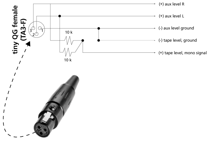
The addition of a mono microphone-level output to the 302 is a beneficial enhancement for connecting transcription recorders, Comtek transmitters, and other inputs. The accompanying diagram demonstrates the correct wiring to create a mono microphone-level output from the tape...

This power supply is based on the 7805 IC regulator, which provides a regulated output voltage ranging from 5 V to 15 V DC, adjustable by a preset resistor. The maximum output current of this power supply is 350...
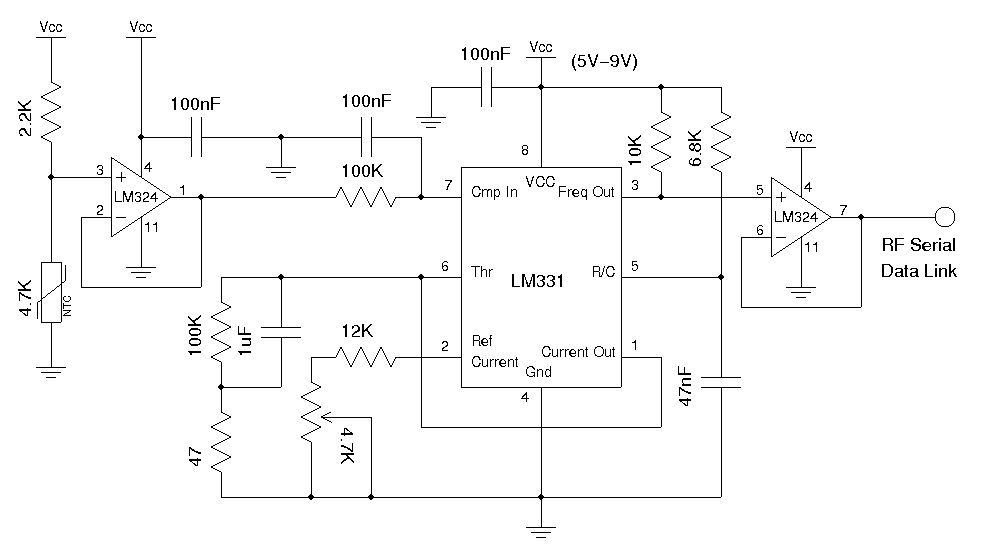
A wireless temperature sensor allows temperature measurements to be taken anywhere within the range of the transmitter and receiver. One straightforward approach to achieve this is by utilizing a voltage-to-frequency conversion chip in conjunction with an analog temperature sensor,...
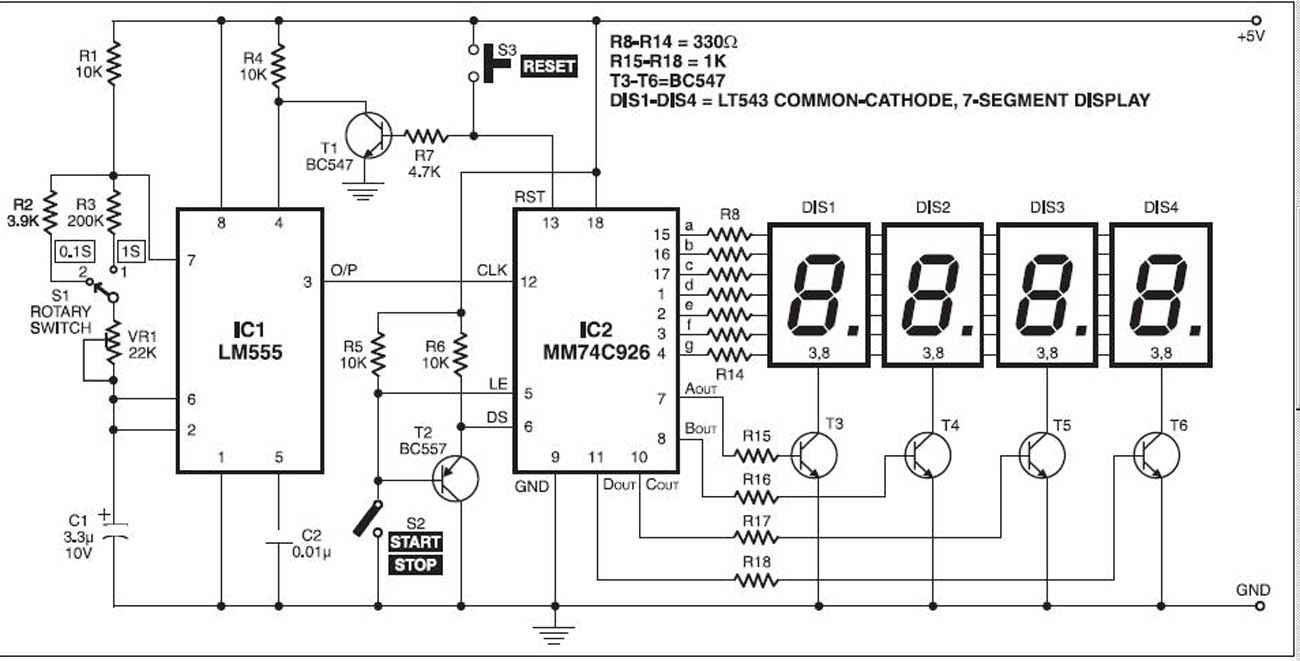
The stopwatch is constructed using a digital timer IC LM555 and an MM74C926 4-digit counter with a multiplexed 7-segment LED display. The MM74C926 features a 4-digit counter, an internal output latch, NPN output for controlling the common cathode source...
This circuit is a motion detection sensor that utilizes a light source and detector as an infrared motion detector. It incorporates components such as a light-emitting diode (LED), a phototransistor, a transmitter, a receiver, an NE555 timer configured as...