
Audio Compressor Circuit with SSM2165

The audio compressor circuit utilizing the SSM2165 IC is designed to manage audio signal levels by reducing the dynamic range of the input signal. The SSM2165 is a low-voltage audio compressor that provides a cost-effective solution for audio applications requiring compression, such as in mixing consoles, broadcast audio, and musical instrument amplifiers.
The schematic typically includes the SSM2165 IC, which handles the compression process. Input audio signals are fed into the IC, where they are processed according to the compression ratio set by external components. The capacitor plays a crucial role in this circuit, as it affects the attack and release times of the compressor. Selecting the appropriate capacitance value is essential for achieving the desired response characteristics.
In addition to the capacitor, resistors are also used to set the threshold and gain of the compressor. The output of the SSM2165 is connected to an output stage, which may include additional filtering or amplification stages to ensure that the audio signal is suitable for further processing or amplification.
Power supply considerations are important, as the SSM2165 operates within a specific voltage range. Adequate decoupling capacitors should be placed near the power pins of the IC to maintain stable operation and minimize noise.
Overall, this simple audio compressor circuit is effective for controlling audio levels, enhancing sound quality, and preventing distortion in audio signals, making it a valuable tool in various audio processing applications.A very simple audio compressor built with SSM2165 IC. There is no much explication about this compressor circuit schematic, just pay attention at capacitor.. 🔗 External reference
Related Circuits
18W audio amplifier constructed using transistors. The 18W audio amplifier design utilizes a transistor-based configuration to achieve efficient amplification of audio signals. The circuit typically consists of several stages, including a preamplifier stage, a driver stage, and a power output...

This document outlines the design process of a control circuit for a stepper motor. Given the characteristics of the stepper motor, the control circuit was developed as a state machine that transitions through four output states depending on two...
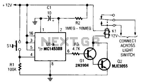
A normally open pushbutton switch (SI) provides a positive input pulse to pin 4 of U1, activating the integrated circuit (IC). The output from U1 at pin 6 delivers base-drive current to a Darlington pair consisting of Q1 and...
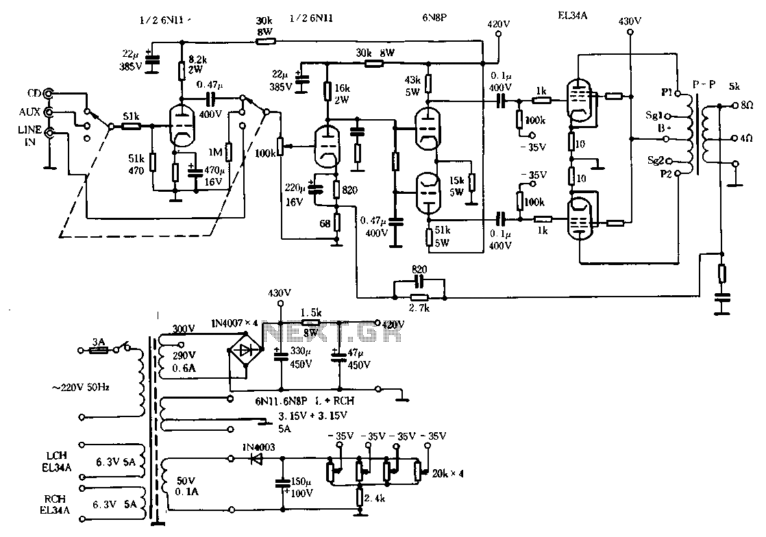
The Ml00 circuit is a typical tube circuit, functioning as a preamplifier. Its input stage utilizes a common cathode amplifier, followed by an inverter stage, culminating in a power amplifier that has been enhanced from a standard connection. This...
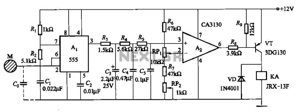
The circuit utilizes a 555 IC in conjunction with capacitors C1, C2, and a metal plate (tablet) M to create a distributed capacitance Co and resistor R1 connected to ground. Resistor R2 forms a self-excited multivibrator, while resistors R3...
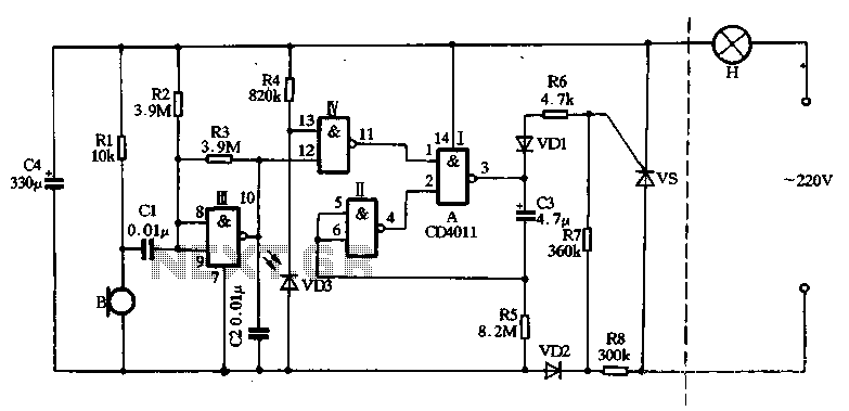
The main circuit utilizes a two-input NAND gate composed of four digital integrated circuits. This includes a NAND gate microphone amplifier circuit, a light control mechanism using an "AND gate," and a monostable delay control circuit formed by NAND...