
This paper describes the process by which a control circuit for a stepper-motor was designed

The control circuit for the stepper motor is fundamentally structured as a finite state machine (FSM), which effectively manages the sequencing of the motor's movements. The state machine architecture allows for precise control over the motor's stepping behavior, crucial for applications requiring high accuracy and repeatability.
In this design, the two input conditions play a vital role. The "direction" input determines the rotational direction of the stepper motor, allowing it to move either clockwise or counterclockwise. The "enable" input serves to activate or deactivate the motor control, ensuring that the motor only operates when required.
The state machine comprises four distinct states, each corresponding to a specific step in the motor's operation. These states are typically labeled as State 0, State 1, State 2, and State 3. Each state transition is triggered by the combination of the input signals, which dictates the next state based on the current state.
For example, if the motor is in State 0 and the direction input indicates a clockwise movement while the enable input is active, the state machine transitions to State 1. This process continues through the states, with each transition resulting in a specific output signal sent to the motor driver, which ultimately controls the motor's coils to achieve the desired movement.
The design of the control circuit may utilize various electronic components, including microcontrollers or dedicated state machine ICs, to implement the logic required for state transitions. Additionally, feedback mechanisms can be integrated into the circuit to monitor the motor's position, further enhancing the control precision.
Overall, this stepper motor control circuit design exemplifies the application of state machine principles in electronic engineering, providing a robust solution for controlling stepper motors in a variety of automation and robotics applications.This paper describes the process by which a control circuit for a stepper-motor was designed. Due to the nature of the stepper motor, the control circuit had to be a state machine that cycled through four output states based on two input conditions (direction and enable) 🔗 External reference
Related Circuits
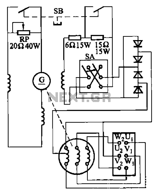
The AX3-300-2 DC arc welding machine circuit is part of the AX, AX1, AX3, and AR series of rotary DC arc welding machines. These machines share a similar structural design, featuring a three-integral unit configuration that combines an inverter...
This universal power supply includes a bridge rectifier, a voltage stabilizer (78xx), and a PNP power transistor. This combination allows for a load current output. The universal power supply circuit is designed to convert alternating current (AC) from the mains...
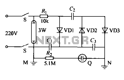
The IED functions as a hotel, restaurant, and family-oriented tool designed for the effective eradication of mosquitoes, as illustrated in Figure 16-12a. It employs a diode voltage doubler rectifier circuit to generate a high voltage. When mosquitoes are attracted...
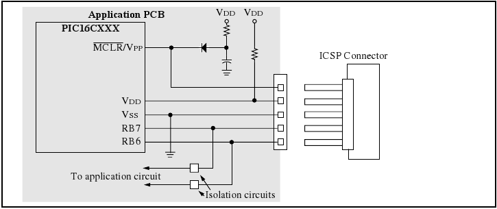
The programmer utilizes a serial signaling scheme to program the chip while it is in-circuit. The signaling is transmitted through the programming clock (PGC or ICSPCLK) and the programming data (PGD or ICSPDAT) pins. Additionally, the MCLR/VPP pin serves...
If the offset value exceeds 5mV, adjust this value by experimenting with resistors, starting with 220K, connected from test point Z (the junction of R22 and R23) to +V if there is a negative voltage, or to -V if...
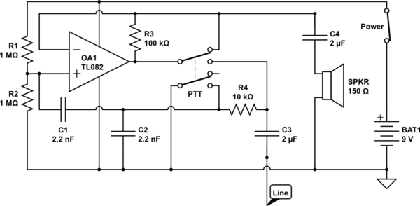
The circuit operates in receive mode, with the Push-To-Talk (PTT) switch enabling transmit mode. The speaker functions as both a microphone and a speaker. Most systems observed utilize a rocking armature transducer for the speaker. There is no base...