
Audio Fading Circuit Using the MAX5456/MAX5457

The application circuit utilizes three stereo digital potentiometers, which are essential components for managing audio levels in a multi-speaker setup. The configuration allows for precise control over volume, balance, and fader settings, making it suitable for complex audio systems.
The circuit is designed to handle four speakers, allowing for an immersive sound experience. Each digital potentiometer is responsible for adjusting specific audio parameters: one for volume control, another for balance between left and right speakers, and the third for adjusting the fader, which can control the relative levels of the front and rear speakers.
The push-button interface provides a user-friendly method for interacting with the circuit. Each button can be assigned to specific functions such as increasing or decreasing volume, adjusting balance, or fading between speakers. The use of digital potentiometers allows for smoother transitions and finer adjustments compared to traditional analog potentiometers.
In terms of implementation, the circuit may include a microcontroller that interfaces with the digital potentiometers. This microcontroller can be programmed to interpret button presses and translate them into appropriate commands for adjusting the potentiometer settings. Additionally, feedback mechanisms such as LED indicators can be incorporated to provide visual confirmation of the current settings.
Overall, this application circuit represents a sophisticated solution for audio control in multi-speaker systems, combining the benefits of digital technology with an intuitive user interface.Application circuit using 3 stereo digital pots to control volume, balance and fader in 4 speaker configuration and push button interface.. 🔗 External reference
Related Circuits
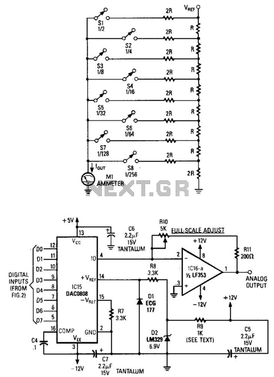
Figure A illustrates an R/2R resistor ladder. Each closed switch increases the current flow. A basic channel A/D converter is depicted in Figure B. The voltage reference (D2) is shared across all channels, although the value of the dropping...
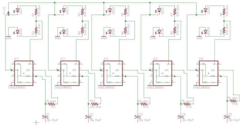
Build a circuit that will flash five pairs of LEDs at variable rates. To achieve this, a circuit utilizing five NE555 timers has been designed. Trim pots will be used to control the variable flash rate. Assistance is needed...
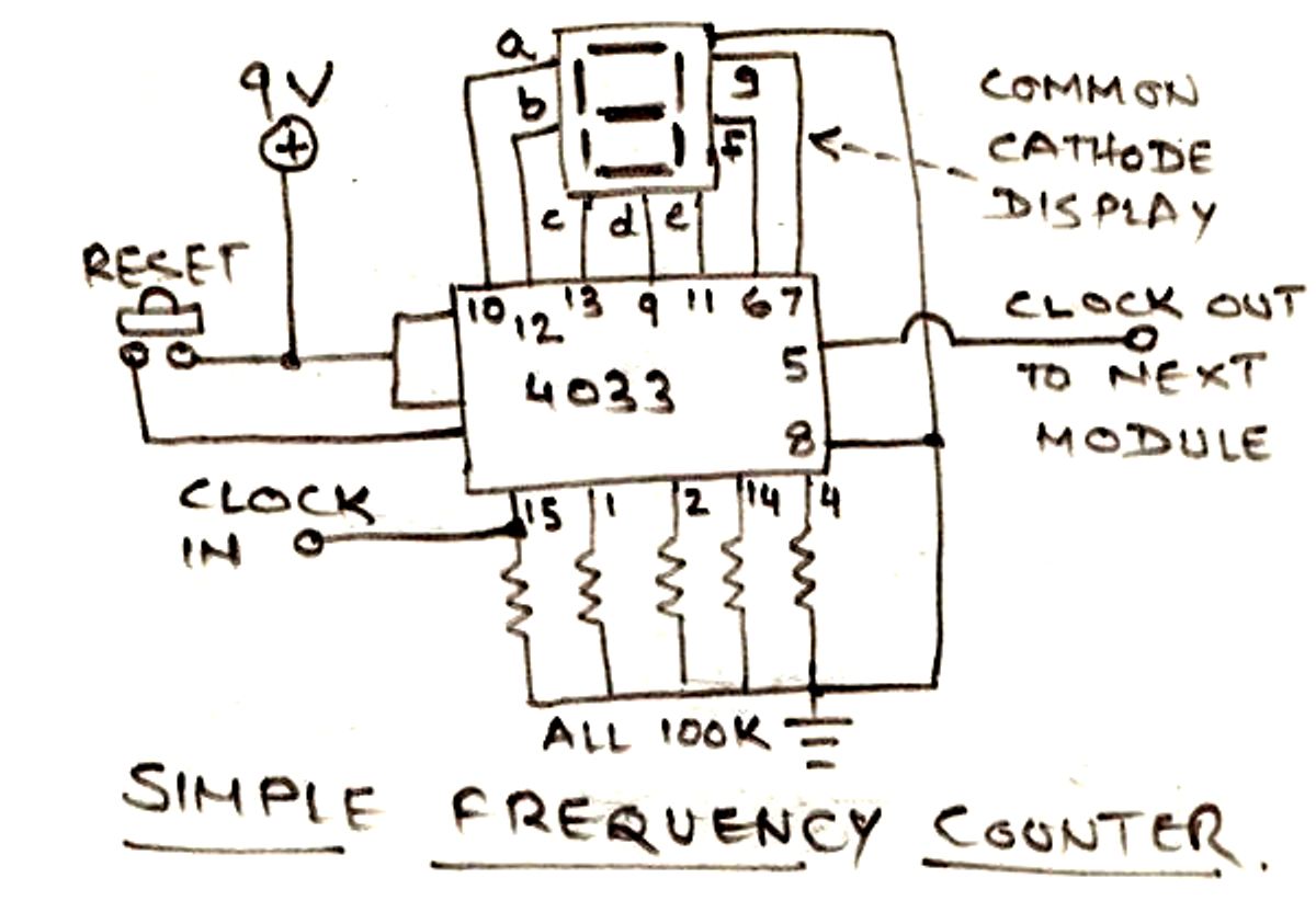
The circuit illustrated below is designed for measuring frequency in Hertz (Hz). It is straightforward to construct, utilizing a single IC 4033 and a common cathode display as the main components. For measuring higher frequencies, typically in the range...
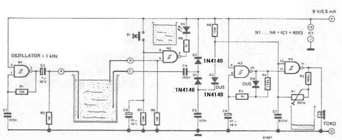
The circuit diagram is straightforward and operates as follows: the N1 Schmitt trigger functions as an oscillator, producing a frequency of approximately 1 kHz. When there is sufficient water in the tank, alternating voltage flows from electrode A to...
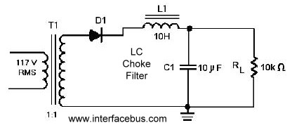
A circuit that utilizes one cycle of alternating current (AC) to produce direct current (DC). A half-wave rectifier circuit generates DC from either the positive or negative cycle of the AC input, but not both. It is important to...
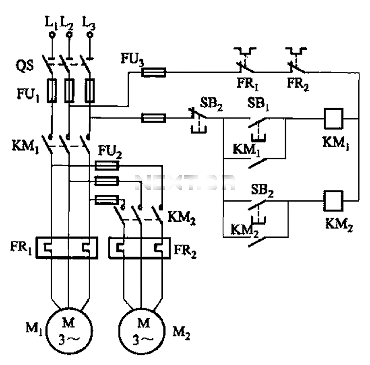
The circuit illustrated in Figure 3-83 demonstrates that the contactor KMi is activated only after it is pulled, which indicates that the motor Mi has started for the first time. Following this, the contactor KM2 is then activated, indicating...