
The main circuit in order to start the control circuit

The circuit operates as a sequential motor control system where the activation of the first motor (Mi) is crucial for the subsequent activation of the second motor (Mz). The contactor KMi serves as a primary control switch that engages the first motor. Upon successful activation of motor Mi, the contactor KM2 is engaged, allowing the second motor (Mz) to start.
The configuration typically includes control relays and overload protection devices to ensure safe operation. For instance, overload relays may be integrated to prevent damage to the motors due to excessive current draw. Additionally, interlocking mechanisms can be utilized to ensure that both motors do not operate simultaneously unless specified, enhancing the safety and reliability of the circuit.
The schematic may also depict auxiliary contacts associated with the contactors, which provide feedback to the control circuit, indicating the operational status of each motor. This feedback is essential for monitoring and controlling the system effectively, enabling the implementation of further automation or control strategies as needed.
In summary, the circuit design emphasizes a controlled startup sequence for multiple motors, minimizing the risk of electrical faults and ensuring efficient operation. Circuit shown in Figure 3-83. The figure shows that only when the contactor KMi after pull (ie, after the motor Mi first start), KM2 to pull (ie Mz after start)
Related Circuits
The following circuit illustrates a fully linear diode sensor circuit diagram. This circuit is based on the A748 integrated circuit (IC). Features include the use of an operational amplifier (op-amp). The fully linear diode sensor circuit utilizes the A748 IC...
This simple DC servo motor circuit design can be utilized in various electronic projects. The circuit schematic illustrates that this DC servo motor driver employs a single integrated circuit along with a few external electronic components. For bidirectional DC...
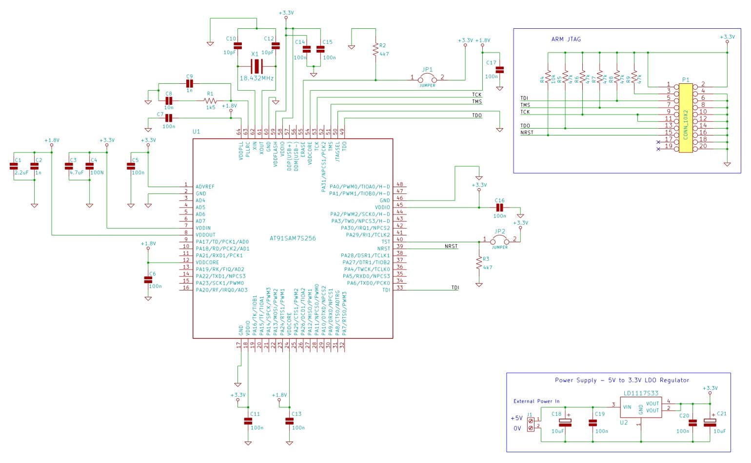
The minimum number of supporting components required to build a circuit using AT91SAM7S microcontrollers. This example uses the AT91SAM7S256 ARM7 microcontroller. To construct a circuit utilizing the AT91SAM7S256 ARM7 microcontroller, a minimal set of supporting components is essential to ensure...
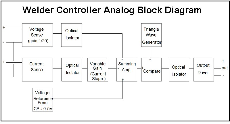
The first board is digitally controlled, while the actual welding current is analog. This design enables real-time operation without requiring the CPU to process the voltage or current. A block diagram illustrates its function: it operates as a switching...
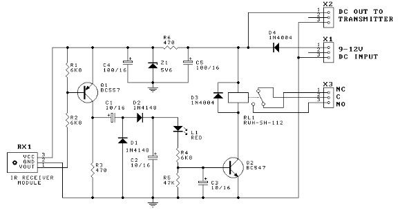
This door minder electronic project is based on a 555 timer circuit and utilizes an infrared (IR) beam to monitor doorways, passageways, or any other designated area. When the IR beam is interrupted, a relay is activated, which can...
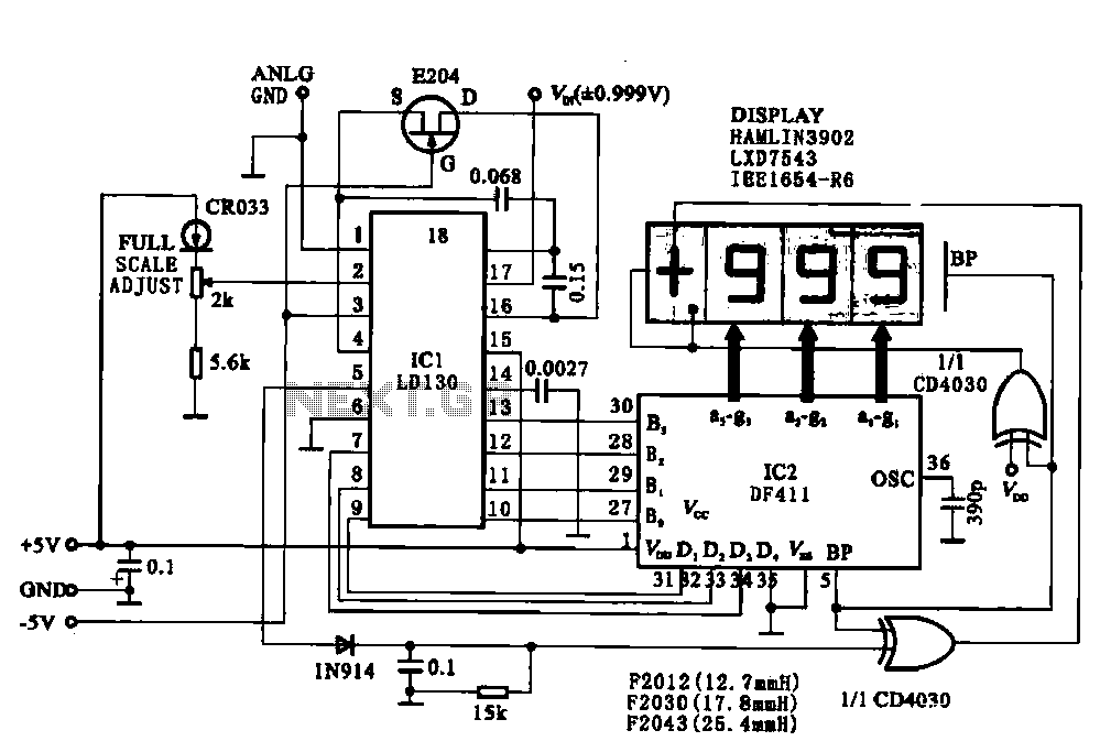
This circuit illustrates a display driving system for a digital voltmeter. The liquid crystal display (LCD) does not emit light by itself; it relies on external incident light for visibility. The integrated circuit (IC) LD130 serves as an input...