
Audio Light Circuit

The described circuit utilizes the LM3915 integrated circuit, which is designed to drive a bar graph display based on an analog input signal. The primary function of this circuit is to activate an output when the sound level surpasses a predetermined threshold, making it suitable for audio level monitoring applications. The LM3915 operates by converting the input voltage into a corresponding output that can be visually represented on a bar graph or LED display.
To handle higher current loads, which may be necessary for driving larger displays or other devices, a transistor is introduced into the circuit. The transistor acts as a switch that allows the LM3915 to control larger currents without exceeding its own output current limitations. In this configuration, the output from the LM3915 drives the base of the transistor, which in turn controls the larger load connected to its collector.
When the sound level exceeds the preset threshold, the LM3915 activates its output, turning on the transistor. This results in the flow of current from the power supply through the load, enabling the desired output action, such as illuminating a display or activating a relay. Proper selection of the transistor is crucial to ensure it can handle the required load current and voltage levels.
In summary, this circuit effectively combines the LM3915 log-output driver with a transistor to create a sound-activated output system capable of managing higher current demands, making it versatile for various electronic applications. This circuit will produce an output when the sound exceeds a preset level. The LM3915 is a log-output bar graph driver. Use the transistor driver shown for higher current loads. To drive heavy-current loads with an LM3915 output, you must add a transistor, as shown in B.
Related Circuits
In this circuit, a simple calculator, in conjunction with a COB (chip-on-board) from an analogue quartz clock, is used to make a telephone call meter. The calculator enables conversion of STD/ISD calls to local call equivalents and always displays...
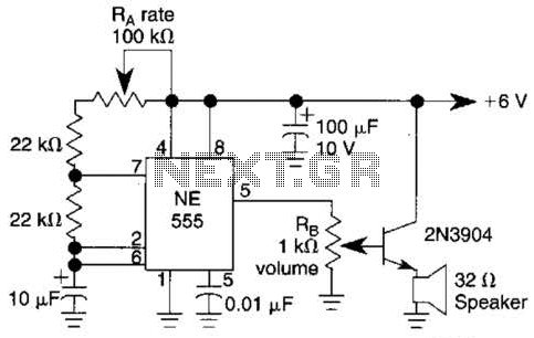
Ra sets the rate while RH sets the volume of clocks in the speaker. The 555 is configured as a low frequency oscillator. The circuit is powered by a 6 V battery. The circuit utilizes a 555 timer IC configured...
This circuit utilizes a 555 timer integrated circuit (IC) to function as an alarm system designed to deter theft of personal belongings, such as luggage, or to prevent unauthorized entry into a residence. The alarm is activated when a...
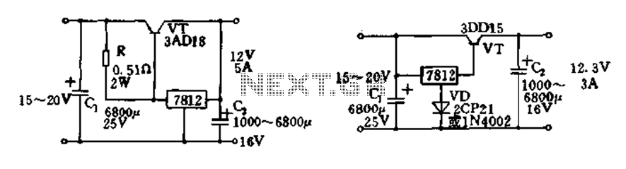
Expand integrated three-terminal regulator block circuit output current method The integrated three-terminal regulator is a versatile component commonly used in power supply circuits to provide a stable output voltage. This regulator typically consists of three terminals: input, output, and ground....

A battery-powered portable unit suitable for all types of televisions. This low-cost project allows audio reproduction from a TV without disturbing others. This battery-powered portable audio unit is designed to provide a convenient solution for reproducing television audio discreetly. The...

Here is a design for a temporary lamp circuit that is very helpful in emergency situations or in any application where there is limited time to turn off the lamp. Simply press the push button to perform a quick...