
Electronic Metronome Circuit

The circuit utilizes a 555 timer IC configured in astable mode to function as a low-frequency oscillator. In this configuration, the timer generates a continuous square wave output, which can be used to drive a speaker, producing sound by modulating the audio signal. The resistors Ra and Rh play crucial roles in determining the frequency and amplitude of the output waveform.
Ra, the resistor connected to the discharge pin and the threshold pin of the 555 timer, influences the rate of oscillation. By adjusting Ra, the time period of the high state of the output can be modified, thus varying the frequency of the oscillation. Rh, on the other hand, is connected to the discharge pin and ground, controlling the volume of the output signal. The combination of these two resistors allows for a customizable sound output, making it suitable for various applications such as alarms, sound effects, or simple audio applications.
The circuit is powered by a 6 V battery, providing sufficient voltage for the operation of the 555 timer and the connected speaker. The choice of a 6 V power supply ensures that the circuit remains efficient and minimizes power consumption while delivering adequate performance. To enhance the output sound, a capacitor may be connected in parallel with the speaker, which can help to smooth out the audio signal and improve the overall sound quality.
Overall, this simple yet effective circuit design demonstrates the versatility of the 555 timer in generating audio signals, with adjustable frequency and volume settings suitable for a variety of electronic projects. Ra sets the rate while RH sets the volume of clocks in the speaker. The 555 is configured as a low frequency oscillator. The circuit is powered by a 6 V battery.
Related Circuits

A field strength meter utilizing a biased Schottky detector employs a temperature-compensated Schottky diode within an amplified, untuned field strength indicator powered by two AA cells. This device indicates the relative field strength of RF fields ranging from a...
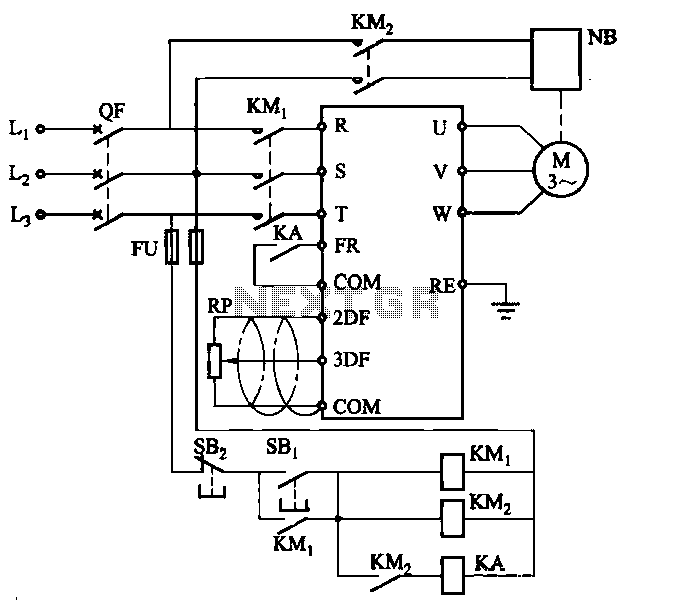
Electromagnetic brake motors consist of a motor and an electromagnetic brake, forming a standard assembly. The circuit diagram is provided. In this configuration, FR represents the forward run and stop command terminal, while the intermediate relay KA is employed...
The circuit functions as a random number generator, producing numbers from 1 to 6. It features a line of LEDs, each corresponding to a number in the range of 1 to 6. When the push button S1 is pressed...
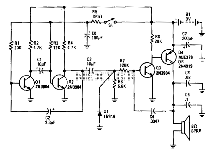
Transistors Q1 and Q2 form the two halves of a free-running multivibrator, with the frequency determined by the voltage across capacitor C8. This capacitor is charged and discharged by the operation of switch S1. Transistors Q3 and Q4 constitute...

Fire alarm circuit using an LDR (Light Dependent Resistor) as a flame sensor. It warns the user about fire accidents by detecting smoke produced during a fire. As smoke passes between an LED and an LDR, the amount of...

A high-quality stereo amplifier circuit of 44 Watts (22 Watts per channel) using the TDA 1554 IC. This is a powerful audio amplifier circuit for 2 channels. The described stereo amplifier circuit utilizes the TDA 1554 integrated circuit (IC), which...