
Audio Mixers Circuits

The described audio mixer circuit is a versatile tool for combining multiple audio sources. It includes three line inputs and three microphone inputs, accommodating a range of low impedance dynamic microphones, specifically those with an impedance between 200 and 1000 ohms. For users who prefer using electret condenser microphones, the circuit allows for this option as well, although it necessitates the inclusion of a biasing resistor to ensure proper operation.
The circuit's design is simplified for ease of use, featuring two dual logarithmic potentiometers that facilitate the adjustment of input signal levels. This allows users to finely tune the audio inputs before they are mixed. The resistors within the circuit play a crucial role in the mixing process, enabling the combination of multiple audio signals into a singular output. The mixer operates passively, meaning it does not require an external power supply, which enhances its portability and ease of integration into various setups.
In applications where telephone equipment needs to be interfaced with the audio mixer, a specific circuit configuration is provided. While this circuit may not perfectly replicate the full characteristics of a traditional telephone network, it is adequate for basic testing and experimentation. For more accurate simulations, adjustments such as using a 600-ohm resistor and increasing the power supply voltage are recommended.
The concept of an audio mixer is fundamental in electronic audio processing. It serves the primary function of summing multiple audio signals, with the output representing the total of all inputs. This is often symbolized in circuit diagrams as a summing node, denoted by a circle with a plus sign. Furthermore, advanced designs may incorporate both mixing and amplification functionalities, utilizing amplifiers equipped with power-down disable features to streamline the circuit's operation and enhance its versatility in various audio applications.The mixer circuit below has 3 line inputs and 3 mic inputs. The mic inputs are suitable for low impedance 200-1000R dynamic microphones. An ECM or condenser mic can also be used, but must have bias applied via a series resistor. Circuit to Connect Telephone Equipment to Audio Mixer - I have used this type of circuits for q uick testing of telephone equipment. This is a quick hack that does not exactly resemble the characteristics of the real telephone network, but is enough for this kind if applications. If you want better simulation, change the resistor to 600 ohm and increase the power supply voltage. Line Mixer (Tomi Engdahl) - The circuit is an audio mixer circuit so simple as it can be. There are two dual logarithmic potentiometers in the circuit to adjust the input signal levels and some resistors to do the actual mixing.
The circuit is totally passive, so no power supply is needed. Simple Line Mixer - Most people reading this would be well aware of what a mixer is used for but I`ll reiterate here. The job of an Audio mixer is to combine various audio signals into a single audio signal. It is better known in electronic terms as a summing circuit. That is to say that the output is the sum of all of the inputs. A summing note is often represented as a circle with a PLUS (+) symbol in it. Low cost circuit incorporates mixing & Amplifying functions - EDN-Design Ideas: Using an amplifier with a power-down disable, you can combine the mixer and the amplifier functions.
🔗 External reference
Related Circuits
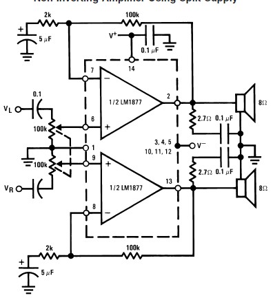
This audio amplifier circuit is designed to deliver 2W per channel continuously into 8-ohm loads. The LM1877 is engineered to function with a minimal number of external components while still offering flexibility for applications in stereo phonographs, tape recorders,...
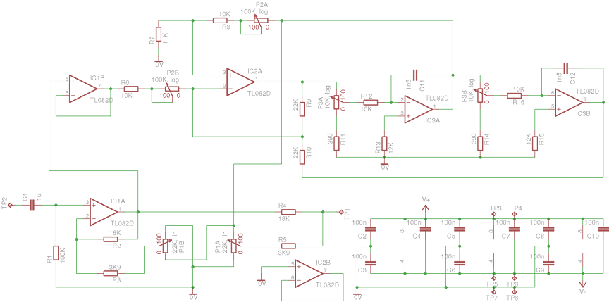
A parametric equalizer on an audio-mixer-sized PCB. The circuit design features a parametric equalizer implemented on a printed circuit board (PCB) sized for integration into an audio mixer. The equalizer allows for precise control over the frequency response of an...
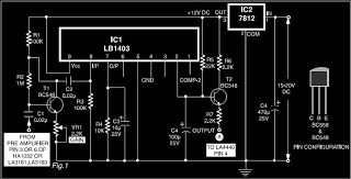
This is a circuit diagram for automatic muting in audio systems utilizing the IC LB1403. The output from a pre-amplifier, such as the LA3160, LA3161, or HA1032, is connected to the base of the amplifier transistor BC548 (T1). A...
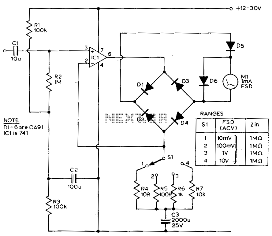
This circuit exhibits a flat frequency response from 8 Hz to 50 kHz, maintaining a -3 dB level at the 10 mV range. Furthermore, while the upper frequency limit remains consistent across less sensitive ranges, the lower frequency limit...

The ongoing debate regarding the superiority of valves versus transistors is not the focus here. However, for those undecided, this simple amplifier serves as an excellent test. It employs a valve as a pre-amplifier and a MOSFET in the...
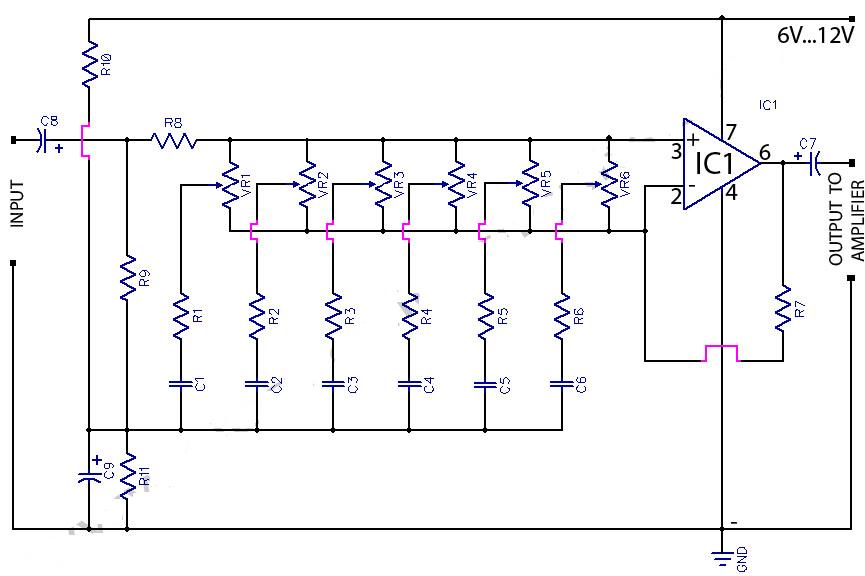
This circuit is a 6-band graphic equalizer that allows for the adjustment of low, medium, and high frequencies using the operational amplifier circuit 741. It enables control and mixing of frequencies and tones according to user preferences. The audible...