
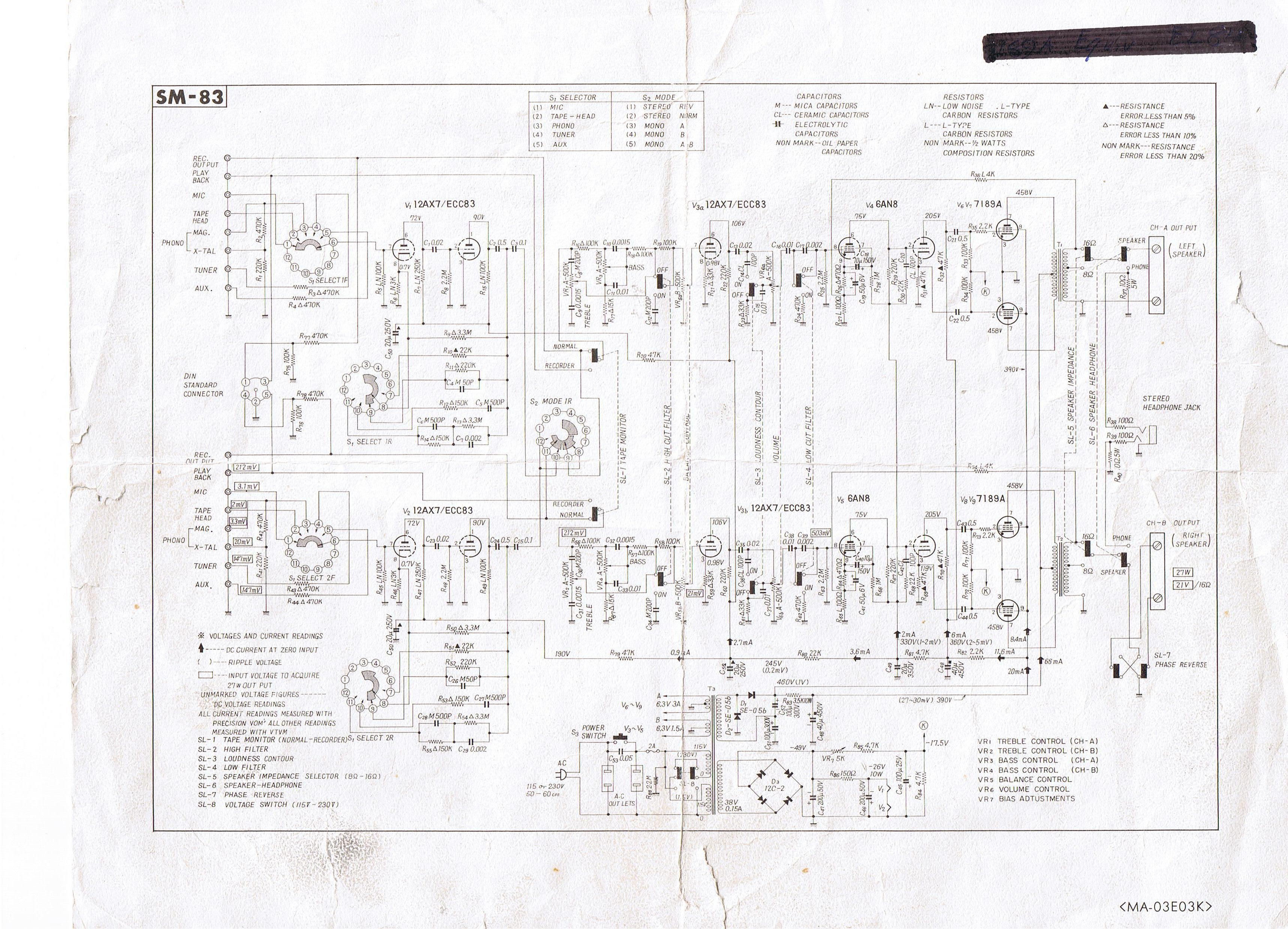
Audio Odd Block KT88 Series 1 Tube Amp-Power Supply

The schematic presents a detailed layout for the ability accumulation system, which is integral to the overall amplifier design. The IEC inlet serves as the primary entry point for mains voltage, ensuring safety and compliance with electrical standards. The inclusion of a 3 Ampere fuse provides overcurrent protection, while the EMI filter mitigates electromagnetic interference, enhancing the performance and reliability of the amplifier.
The power transformer plays a critical role in voltage conversion, delivering the specified dual high-voltage outputs of 180V and a low-voltage output of 12V. The use of an OEM transformer from Edcor ensures that the design meets the necessary specifications for optimal performance. The power supply capacitors, selected for their high voltage rating and reliability, are crucial for filtering and stabilizing the DC voltage supplied to the amplifier's circuitry.
The Vishay/Dale wire wound resistors are chosen for their ability to handle high power dissipation, ensuring stability during operation. Carbon film resistors are utilized in lower power applications, providing accuracy and low noise characteristics. The rectification of the High-Tension supply is achieved through the STTH5 ultrafast rectifiers, which facilitate rapid switching and minimize voltage drop, thus improving overall efficiency.
CRC filtering is employed to smooth out the rectified voltage, reducing ripple and providing a stable DC output. The 12V DC supply for tube heaters is essential for maintaining the required operating temperature of the tubes, contributing to the amplifier's performance. The adjustable delay circuit is a valuable feature that protects the amplifier’s components during power-up, allowing the system to stabilize before applying high voltage to the tubes, thereby prolonging their lifespan and enhancing reliability.
In summary, the schematic provides a comprehensive overview of the ability accumulation system, integrating various components that work together to deliver reliable and efficient performance in the amplifier design.A schematic of the ability accumulation is apparent below. Like the amplifier schematic, the ability accumulation ambit is © OddWatt Audio and permission to host the schematic on this armpit has been provided by OddWatt Audio. You are chargeless to use the schematic for personal, non-commercial use. Mains ability enters the amplifier through an I EC atrium amid at the rear of the amp. The IEC atrium includes a 3 Ampere agglutinate and an EMI filter. The ability agent is an OEM bogus by Edcor with ratings of 180V-0-180V at 250 mA and 12V at 4A. Ability accumulation capacitors are Panasonic ECG alternation 500 volt electrolytic and Solen Polypropyene. The ample ability resistors are Vishay/Dale wire anguish and the actual resistors are carbon film. The High-Tension (HT) accumulation is rectified with STTH5 ultrafast aerial voltage rectifiers and uses CRC filtering.
A 12V DC accumulation is acclimated for the tube heaters. An adjustable adjournment ambit is acclimated to adjournment the HT accumulation on ability up. 🔗 External reference
Related Circuits
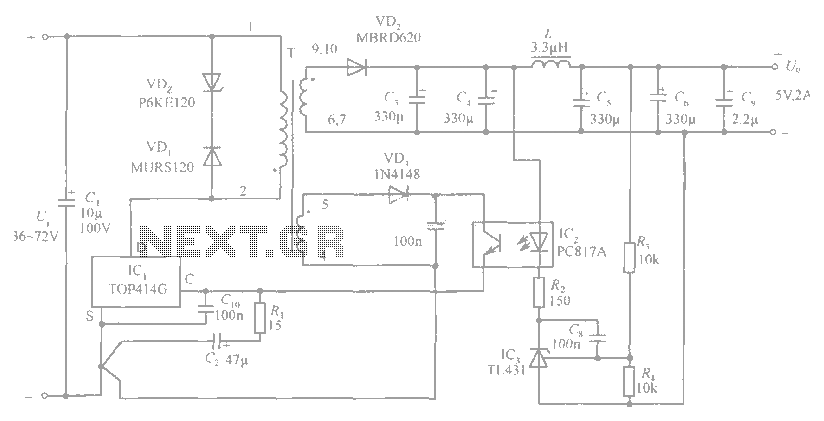
The circuit diagram includes an input filter capacitor C1 and a primary clamp composed of VDz and VD1. The resistor R1 is connected to the control terminal. C2 serves as a bypass capacitor. The TOP414GC-S is connected in parallel...
This audio mixer circuit schematic is designed around four current-controlled amplifiers, all integrated within the SSM2024 IC. The audio mixer circuit utilizes the SSM2024 integrated circuit, which features low-noise, high-performance operational amplifiers suitable for audio applications. The SSM2024 is particularly...
Figure 1 shows distortion variations in red and violet. Notice how the violet wave follows the green wave perfectly during its positive excursion but falls short of the mark during the negative swing. The red wave is more symmetrical,...
This is a Class D audio amplifier circuit used to control the PWM motor speed. This circuit has two advantages for battery-powered portable devices. First, it provides high efficiency, which extends battery life. The Class D audio amplifier operates by...
After restoring a Fisher 400, the search for another tube amplifier began, motivated by a desire to apply newly acquired skills. Importing equipment from the USA to the European Union proved costly, with shipping fees around $200 to $250,...
This solid-state push-pull single-ended Class A circuit is capable of providing sound quality comparable to that of valve amplifiers. It delivers an output power of 6.9W when measured across an 8 Ohm loudspeaker cabinet load, with reduced total harmonic...