
Voltage Controlled Audio Mixer Circuit

The audio mixer circuit utilizes the SSM2024 integrated circuit, which features low-noise, high-performance operational amplifiers suitable for audio applications. The SSM2024 is particularly advantageous due to its ability to provide high gain with minimal distortion, making it ideal for mixing audio signals from multiple sources.
In this schematic, each of the four amplifiers serves as a channel for audio input, allowing for the mixing of different audio signals. The configuration typically includes input resistors that set the gain for each channel, along with potentiometers to allow for adjustable volume control for each input.
The output of each amplifier can be fed into a summing stage, which combines the individual audio signals into a single output signal. This summing stage is essential for ensuring that the mixed audio maintains a balanced output level and clarity. Capacitors may be included in the output stage to block any DC offset, ensuring that only the AC audio signal is passed to the subsequent processing stages or to the output device.
Power supply considerations are also critical in this design. The SSM2024 requires a dual power supply, typically +15V and -15V, to operate effectively. Proper decoupling capacitors should be placed near the power pins of the IC to filter out any noise that may affect audio quality.
Overall, this audio mixer circuit schematic provides a robust solution for mixing multiple audio signals, leveraging the capabilities of the SSM2024 integrated circuit to achieve high fidelity and low distortion in the final output.This audio mixer circuit schematic we propose here is built around four amplifiers, which are current controlled, all of them incorporated in IC SSM2024, p.. 🔗 External reference
Related Circuits
This circuit is designed for applications where over-current protection is necessary. An example can be found in the model train hobby. Experienced model train enthusiasts understand that troubleshooting a short-circuit can be quite challenging. While it is relatively easy...
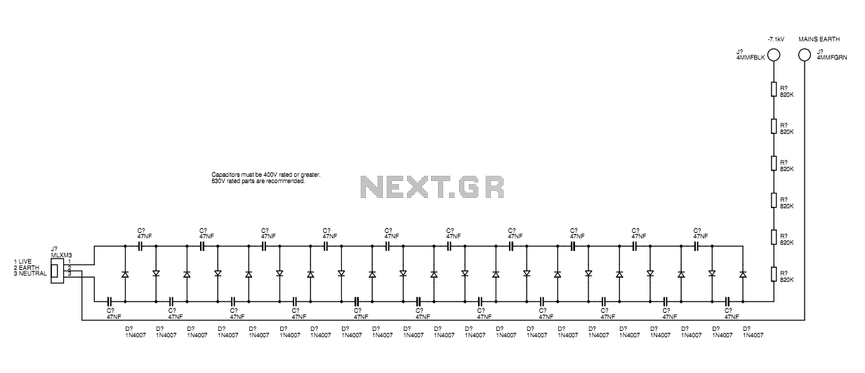
A basic mains driven Cockroft ladder high voltage generator is shown in the schematic. This is functionally the same as a project in Electronics Today International many years ago. The peak mains voltage of 340V appears across each capacitor...
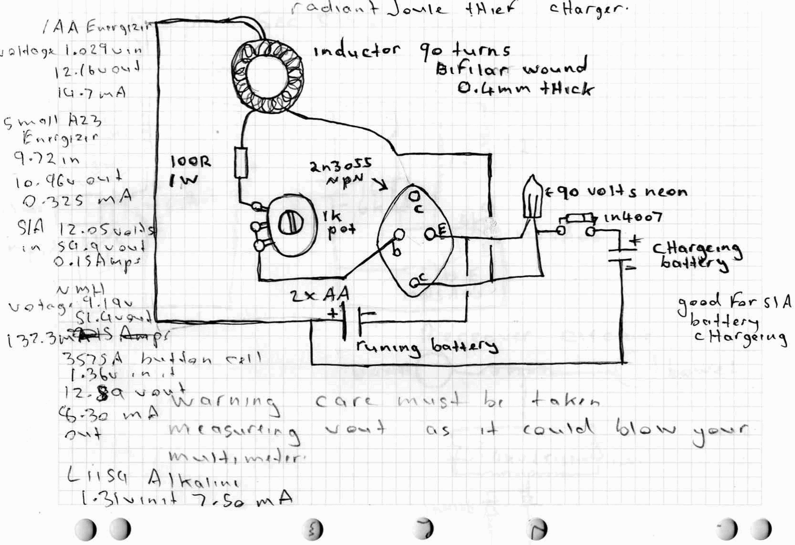
A high power joule thief circuit is explained in this post, which can be constructed by any new hobbyist. Here is the simplified drawing of the radiant joule thief battery charger. The inductor was wound with many turns until...
This DC voltage doubler circuit generates a voltage that is double the input supply voltage. It is beneficial when a higher voltage is required from a single lower voltage power source, particularly in applications with low current consumption. The DC...
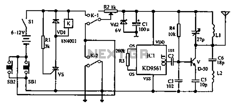
As environmental awareness increases, electric cars have become an essential part of people's transportation. Preventing electric car theft is a significant concern for owners. Various electric vehicle anti-theft locks have been developed; however, theft of electric cars continues to...
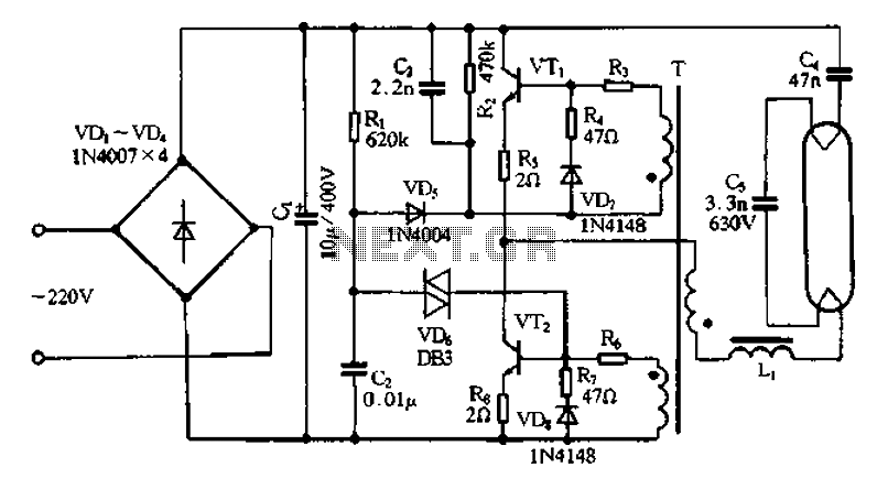
Bridge rectifier circuit in the electronic ballast application circuit The bridge rectifier circuit is a crucial component in electronic ballast applications, primarily utilized for converting alternating current (AC) to direct current (DC). This conversion is essential for powering various electronic...