
audio peak detector

This audio peak detector circuit is designed to visually indicate audio signal peaks from stereo channels using a single LED. The core of the circuit is based on the 4093 IC, which contains multiple Schmitt trigger NAND gates. Each channel's signal is processed identically, ensuring consistent performance.
The threshold for detecting peaks is adjustable via the preset resistor P1. This allows for calibration based on the specific audio signal characteristics, accommodating different audio sources and levels. The high impedance bias provided by R2 (R1) allows for the audio signal to be superimposed effectively, ensuring that the Schmitt trigger gates respond appropriately to changes in the audio signal.
When the audio signal, combined with the bias voltage, causes the voltage at the input pins of the Schmitt trigger to drop below the defined threshold, the output transitions to a high state. This transition is crucial as it triggers the subsequent stages of the circuit. The output from IC1.A (IC1.B) is fed into IC1.C, which inverts the signal, thereby lighting LED D3 when a peak is detected.
The inclusion of R3 and C1 introduces a delay in the circuit, which is essential for accurately capturing short audio peaks. This delay prevents the LED from flickering due to rapid fluctuations in the audio signal, allowing for a more stable visual indication of audio peaks.
The circuit is designed for ease of use, with initial setup instructions that guide the user to adjust the threshold to ensure proper operation. By applying line-level audio to the RCA connectors, users can effectively monitor audio signals without the need for specialized splitter cables, making this circuit a practical solution for audio peak detection in various applications.This audio peak detector allows a pair of stereo channels to be monitored on a single LED. Identical circuitry is used in the left and right channels. Use is made of the switching levels of Schmitt trigger NAND gates inside the familiar 4093 IC. The threshold level for gate IC1. A (IC1. B) is set with the aid of preset P1, which supplies a high impe dance bias level via R2 (R1). When, owing to the instantaneous level of the audio signal superimposed on the bias voltage by C3 (C2), the dc level at pins 1 and 2 (5 and 6) of the Schmitt trigger gate drops below a certain level, the output of IC1. A (IC1. B) will go High. This level is copied to the input of IC1. C via D2 (D1) and due to the inverting action of IC1. C, LED D3 will light. Network R3-C1 provides some delay to enable very short audio peaks to be reliably indicated. Initially turn the wiper of P1 to the +12 V extreme ” LED D3 should remain out. Then apply line` level audio to K1 and K3, preferably music with lots of peaks (for example, drum n bass).
Carefully adjust P1 until the peaks in the music are indicated by D3. The circuit has double RCA connectors for the left and right channels to obviate the use of those rare and expensive audio splitter (Y`) cables. 🔗 External reference
Related Circuits
This audio amplifier design utilizes two LM3886 chips per channel in a parallel configuration, based on the PA100 parallel amplifier detailed in National Semiconductor's application note AN1192. The amplifier can deliver approximately 50W into an 8-ohm speaker and 100W...
The metal detector circuit includes a fixed frequency oscillator, mixer, detector, detection oscillator, and power amplifier circuit. The fixed frequency oscillator circuit is composed of a ceramic filter (ZC), transistor (V1), resistors (R1 to R4), capacitor (C2), and other...
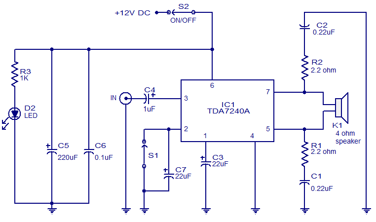
The audio amplifier presented here is based on the TDA7240 integrated circuit from ST Microelectronics. The TDA7240 is capable of delivering 20 watts of audio output power into a 4-ohm load. It requires a minimal number of external components...
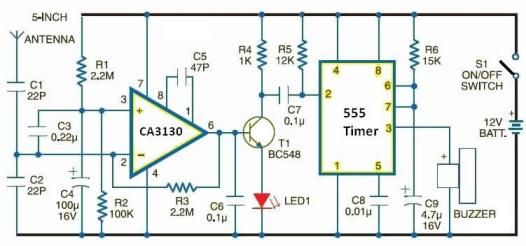
This electronic schematic allows for the design of a simple cellular phone detector circuit capable of sensing the presence of an activated mobile phone from a distance of 1.5 meters. The capacitor C3 should have lead lengths of 18...
A simple audio amplifier application using a TL431 voltage regulator. The amplifier is designed to produce room-filling sound from a standard clear radio equipped with a long-wire antenna and suitable ground. The chip is similar in complexity to a...

Carefully use a small screwdriver to work around the microphone element's rubber boot and gently remove it from the microphone's front casing. Take your time, as there is a spot near the top of the microphone housing where the...