
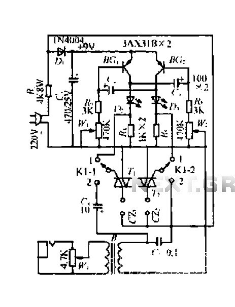
Metal detector circuit diagram 1

The metal detector circuit is designed to identify metallic objects by employing a variety of electronic components that work together to generate and process signals. The fixed frequency oscillator produces a stable frequency output, which is essential for the detection process. The ceramic filter (ZC) ensures that only specific frequency ranges are passed through, while the transistor (V1) amplifies the signal. Resistors (R1 to R4) and capacitor (C2) are used to set the operating point and filter the output, respectively.
The mixer component, utilizing mixer tube (V2), combines the output from the fixed frequency oscillator with the detection oscillator's signal. Capacitor (C3) and resistors (R5 to R8) are utilized to condition the signals for optimal mixing, ensuring that the resulting signal contains the necessary frequency components for detection.
The detector section is critical, as it converts the mixed signals into a form that can be analyzed for the presence of metals. Diodes (VD1, VD2) rectify the signal, while capacitors (C8 to C12) and resistor (R12) smooth and filter the output. The potentiometer (RP) allows for sensitivity adjustments, enabling the user to fine-tune the detector's response to different metal types and sizes.
The detection oscillator generates a signal that varies with the presence of metallic objects, utilizing transistor (V3), inductance coil (L), capacitors (C4 to C7, C19), and resistors (R9 to R11) to form a feedback loop that enhances the detection capability. This section is vital for differentiating between various types of metals based on their unique electromagnetic responses.
Finally, the audio amplifier section converts the detected signals into audible sounds. The power amplifier integrated circuit (IC) drives the speaker (BL) with sufficient power, while resistors (R13 to R15) and capacitors (C13 to C18) are used to filter and amplify the audio signals, ensuring clear sound output for the user.
Overall, the metal detector circuit is a complex assembly of components that work in tandem to effectively detect metallic objects, making it a valuable tool for various applications, including treasure hunting and security screening.The metal detector circuit consists of the fixed frequency oscillator, mixer, detector, detection oscillator and power amplifier circuit, and the circuit is shown as the chart. Fixed frequency oscillator circuit consists of ceramic filter ZC, transistor VI and resistors R1 ~ R4, capacitor C2 and so on.
Mixer consists of the mixer tube V2 and capac itor C3, resistors R5 ~ R8. Detector is composed of the diodes VD1, VD2, capacitors C8 ~ C12 and resistor R12, potentiometer RP and other components. Detection oscillator is composed of the transistor V3, inductance coil L, capacitors C4 ~ C7, C19 and resistors R9 ~ R11.
Audio amplifier is composed of power amplifier integrated circuit IC, resistors R13 ~ R15, capacitors C13 ~ C18 and speaker BL. 🔗 External reference
Related Circuits
A 220V mains power supply is reduced using a control circuit designed by N. Guanidine D. Yi. The circuit features a spike Bode and provides a +9V voltage supply. It includes components such as a control port (G), a...
This device emits intermittent beeping for approximately two seconds when a whistle is detected within a range of several meters. The first two inverters in IC1 function as audio amplifiers. IC1A consistently amplifies the signal captured by a small...
The SheevaPlug is known to have a suboptimal power supply, particularly affecting users in the UK operating at 240VAC. Additionally, heavy loads on the USB can cause issues, especially when connecting an external mechanical disk drive. This project aims...

A dimming control circuit generates a dimming control signal to determine the brightness of at least one light-emitting diode. The dimming control signal consists of multiple bright-dark cycles, each comprising a bright phase and a dark phase. The bright...
A truly timeless circuit. The LM317 is a versatile and highly efficient 1.2-37V voltage regulator that can provide up to 1.5A of current with a large heat sink. It is ideal for just about any application. This was the...
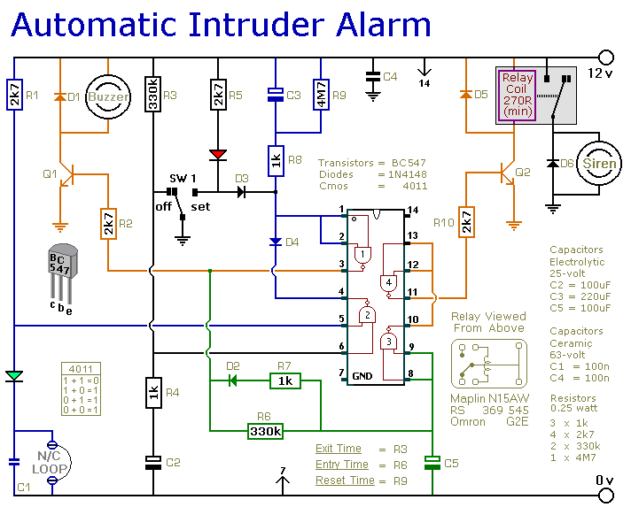
This is a simple single-zone burglar alarm circuit. Its features include automatic exit and entry delays and a timed bell/siren cut-off. It is designed to be used with the usual types of normally-closed input devices such as magnetic reed...