
Audio Reproduction on HCS12 Microcontrollers with Pulse-Width Modulation (PWM) Capability
 Capability")
To implement digital-to-analog conversion (DAC) in systems utilizing the HCS12 microcontroller, an external DAC IC must be integrated into the circuit. The choice of DAC IC will depend on several factors, including the required resolution, output voltage range, and communication interface.
For example, a commonly used DAC is the MCP4725, which is a 12-bit DAC that communicates via the I2C protocol. It allows for easy interfacing with the HCS12 microcontroller, enabling the microcontroller to send digital signals to the DAC, which then converts these signals into corresponding analog voltages.
The typical connection scheme involves connecting the I2C data (SDA) and clock (SCL) lines from the HCS12 to the corresponding pins on the MCP4725. Additionally, the power supply pins of the DAC must be connected to the appropriate voltage levels, typically 3.3V or 5V, depending on the specifications of both the microcontroller and the DAC.
Furthermore, a bypass capacitor may be placed close to the power pins of the DAC to filter out any noise and ensure stable operation. The output of the DAC can be connected to an analog load, such as an audio amplifier or a control circuit, depending on the application requirements.
In summary, while the HCS12 microcontroller lacks built-in DAC capabilities, it can effectively utilize external DAC ICs to achieve desired analog output functionality, thereby enhancing its versatility in various electronic applications.The HCS12 series of microcontrollers does not support dedicated internal digital-to-analogue conversion hardware, and thus external hardware, perhaps in the form of a digital-to-analogue conversion IC. 🔗 External reference
Related Circuits
The internal mute circuit and pre-set gain resistors provide a cost-effective design solution. Output power specifications at both 20V and 24V supplies, along with a low external component count, offer significant value to consumer electronic manufacturers for stereo TV...
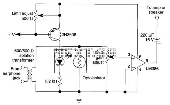
An optoisolator is utilized as an attenuator in this circuit. When the LM386 draws more current from audio signals, the 2N3638 activates, which biases the optoisolator on, thereby reducing the volume. The circuit employs an optoisolator to achieve signal attenuation,...

A passive high-pass filter has been added after the output of the operational amplifier (op-amp) to eliminate DC offset, with the op-amp powered by +12V and the negative supply at 0V. A feedback resistor (Rf) of 500K Ohms is...
Commercial FM demodulation occurs at an intermediate frequency (IF) of 10.7 MHz. With a frequency deviation of ±75 kHz, the deviation of the IF carrier is approximately ±0.7%. This deviation allows for the conversion of FM to AM or...
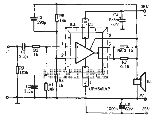
The Burr-Brown OPA541 chip is a power amplifier capable of operating with a maximum power supply voltage of 40V, delivering a continuous output current of up to 5A. The output current can be adjusted using an external resistor to...
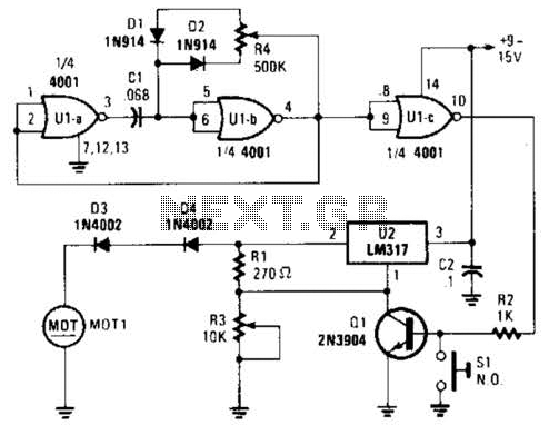
Connected in this manner, an LM317 1-A adjustable-voltage regulator can be utilized to control the speed of a miniature DC motor or to adjust the brightness of a small lamp. The circuit achieves this by modulating the pulse width,...