
op amp Reducing noise in audio circuit (optical pickup + op amp)
")
The described circuit integrates a photodiode and an LED, with the op-amp configured to amplify the current generated by the photodiode in response to light intensity changes. The passive high-pass filter serves to block any DC signals, allowing only AC signals—representative of modulated light intensity—to pass through to the output. This configuration is essential for applications where accurate signal representation is critical, such as audio signal processing.
The choice of a 500K Ohm feedback resistor (Rf) may contribute to excessive gain, potentially leading to increased susceptibility to noise, including thermal noise and electromagnetic interference. The use of a guitar cable as a connection medium introduces additional capacitance and inductance, which can further exacerbate noise issues by acting as an antenna for ambient electromagnetic fields.
To mitigate these noise problems, several strategies can be employed. Shielded cables should be considered to reduce electromagnetic interference, particularly in environments with high levels of noise. Additionally, implementing a differential signaling approach may help to cancel out common-mode noise. The positioning of the photodiode should be optimized to minimize exposure to stray light sources and electromagnetic fields, ensuring that the light source remains consistent and focused. Finally, the circuit can benefit from the inclusion of additional filtering stages or noise reduction techniques, such as low-pass filters or digital signal processing, to further enhance the signal-to-noise ratio.Except that I`ve added a passive high-pass filter after the output of the op-amp, to eliminate DC (since I am using 0V and +12V as my V- and V+, respectively). I use Rf=500K Ohm (is this way too much ). In addition, I have an LED adjacent to the photodiode that serves as a light source. The LED is powered by 5V and the op-amp is powered by 12V, bo th from a PC power supply. The photodiode and LED are connected to the circuit using a 2m long guitar cable ("PL"). The circuit works and produces audio signal when I modulate the intensity of the light shining on the photodiode, but my problem is that the signal is very noisy. I can hear/see two types of noise: Electrical noise similar to a noisy electric guitar pickup. I suspect that it originates in the long cable (or the tip of it, where the photodiode and the LED are conected) collecting ambient electromagnetic noise.
This noise is present all the time, even when no light is shining on the photodiode. Another noise is present only when a signal is generated, i. e only when I modulate the light intensity. I suspect it is a result of amplifying thermal noise, since my gain is very high. Improving the signal to noise ratio at the source, i. e by optimizing the physical conditions (ambient light, precision of the position of the photodiode, etc. ). 🔗 External reference
Related Circuits
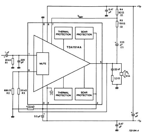
The TDA1514 audio amplifier circuit design is an electronic project capable of delivering high audio power output using a specialized audio integrated circuit (IC) and a few common components. Manufactured by Philips Semiconductor, the TDA1514 audio IC can provide...

Often, there is a need for an additional telephone ringer in an adjoining room to be alerted about incoming calls. For instance, if the telephone is situated in the drawing room, an extra ringer may be required in the...
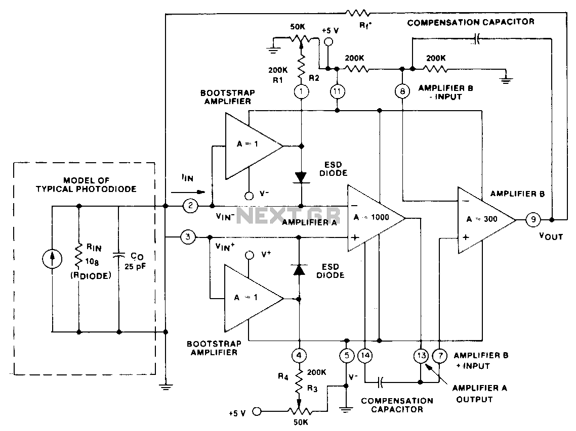
This circuit utilizes a CA5422 dual BiMOS microprocessor operational amplifier. The bootstrap amplifiers reduce bias currents while providing electrostatic discharge protection. Additionally, the potentiometers and their corresponding resistors, R1 through R4, allow the user to adjust bias currents to...
Related components PDF download: ICL7106CD4036. The LCD electronic thermometer circuit is illustrated. The temperature sensor KTY10 exhibits a strong linear relationship between temperature and resistance. Points A and B (Measurement display circuit) can be connected with a 100-meter wire....
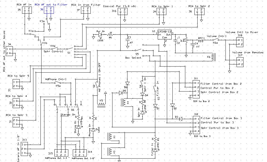
An audio mixer receives outputs from various audio sources and amplifies them to drive a common speaker, allowing all active radios to be heard through a single speaker. However, there is a need for a master Audio On/Off switch...
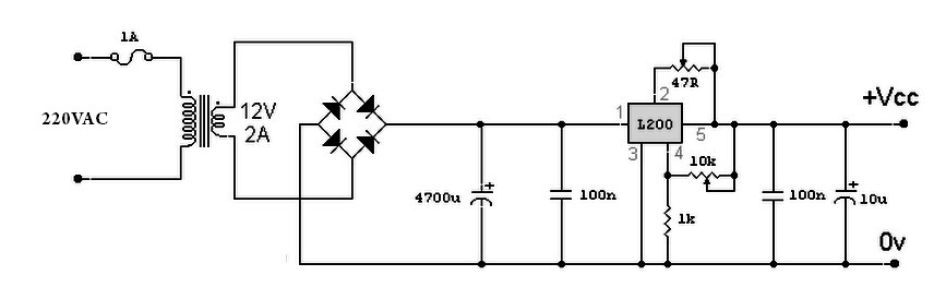
A variable power supply based on the L200 IC, where the output voltage is controlled by a 10K variable resistor. The output voltage ranges from approximately 3 to 15 volts, with a current output ranging from a minimum of...