
Audio Speaker Crossover Circuit

The audio crossover network is a critical component in multi-driver speaker systems, ensuring that each speaker driver operates within its optimal frequency range. The low-pass filter is designed to direct low-frequency signals to the woofer, which is adept at producing bass sounds. The inductor L1, acting as a low-pass filter, increases its reactance with frequency, effectively blocking high-frequency signals and allowing only the desired low frequencies to pass through to the woofer. Capacitor C1, connected in parallel, complements this by presenting higher impedance at lower frequencies, ensuring maximum energy transfer to the woofer.
Conversely, the high-pass filter is configured to facilitate high-frequency signals to the tweeter. In this configuration, capacitor C2 blocks low-frequency signals, while inductor L2 allows high-frequency signals to be transmitted to the tweeter. This arrangement is essential for achieving clarity and detail in the high-frequency range, which is critical for reproducing vocals and high-pitched instruments accurately.
The crossover frequencies are carefully chosen based on the characteristics of the drivers used, ensuring a smooth transition between frequency ranges. The specified crossover points of 700 Hz, 5000 Hz, and 10,000 Hz for the KL-777A speakers provide a balanced sound profile across bass, midrange, and treble frequencies. The 12 dB/octave slope indicates a gradual roll-off, which helps to minimize phase issues and provide a more coherent soundstage.
In designing a crossover network, the choice of component values is essential. Inductors and capacitors can be selected from a range of standard values, with 1 mH for inductors and 16 µF for capacitors being common choices. The specific values can be adjusted based on the desired performance characteristics and the acoustic environment.
Overall, the implementation of a crossover network is fundamental in multi-way speaker designs, ensuring that each driver operates efficiently within its designated frequency range, thus enhancing the overall sound quality and listening experience.An audio cross-over network is used inside a speaker to separate or filter audio signals of different frequencies to different speakers within a speaker cabinet designed to handle those frequencies. This particular crossover network uses two passive components for each filter. The low-pass filter is comprised of inductor L1 and capacitor C1, and i s designed to pass low frequencies to a bass speaker or woofer. The series inductor [L1] tends to block high frequencies [XL increases], while passing low frequencies. At the same time the impedance of the parallel capacitor C1 is higher at lower frequencies. So at low frequencies the capacitor passes all the energy to the speaker, but as the frequency grows more energy is lost over the inductor, passing less energy to the speaker.
The high-pass filter is comprised of inductor L2 and capacitor C2, and is designed to pass high frequencies to a tweeter. The series capacitor C2 blocks or attenuates low frequencies from reaching the speaker, while the inductor L2 passes high frequencies to the speaker.
Reducing the circuit could just leave the capacitor in circuit with the speaker forming a voltage divider. Common values to use include 1mH for the inductors and 16uF for the capacitors. However almost any common value around those ranges will do depending on how fast, or slow, you want the crossover to take place between the speakers and the types of speaker used.
Remember much of how a speaker sounds depends on the room it`s placed in and of course the enclosure or cabinet that`s used. Among the speakers the editor uses include two 4-way, 6-speaker, KL-777A speakers from Kenwood covering the 25 - 22, 000Hz audio frequency range.
The KL777A has a tone selector which changes the sound from soft, normal, or clear [as stated on the knob]. The crossover frequencies are stated at 700Hz, 5000Hz and 10000Hz [Base, Midrange, High range]. The crossover network also states a 12dB / octive change. A set of KL555A have the crossover frequencies stated at 800Hz, 5000Hz, also with a tone selector. Of course some home entertainment speakers, having only one speaker or two of the same type my not have a cross-over network at all.
In any event because the preference is almost user defined, no values are used in the circuit schematic above. The pages provide schematic diagrams for both passive and active circuits, and in some cases a passive circuit that is also used with an active circuit [operational amplifier].
🔗 External reference
Related Circuits
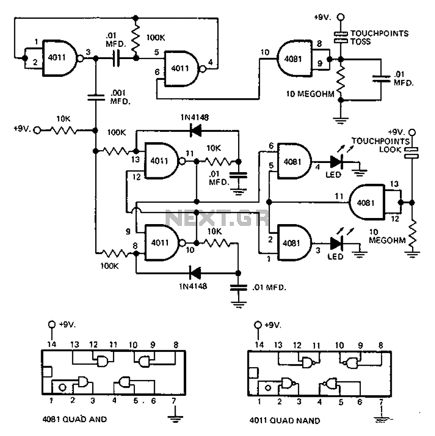
This circuit employs an astable multivibrator to alter the state of a signal based on specific conditions. It also incorporates a flip-flop, which retains the state of the output once a change is detected, completing a cycle of the...
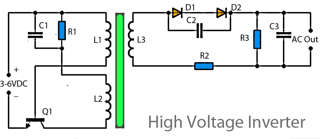
This inverter circuit operates using a transistor and transformer, along with other components, to elevate the voltage. The input supply voltage ranges from 3V to 6V DC, which is then converted to a high voltage AC output. However, the...
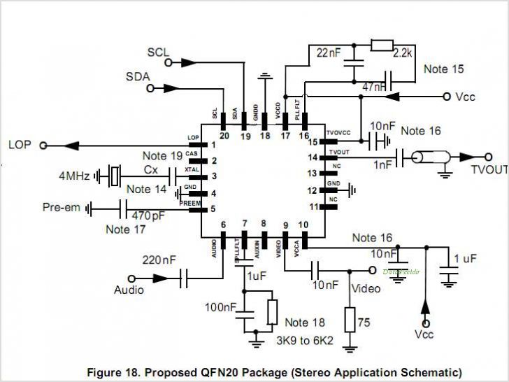
MC44BS374CA: PLL Tuned UHF and VHF Audio Video High Integration Modulator MC44BS374CA The MC44BS374CA Audio and Video Modulator is for use in VCRs, set-top boxes, and similar devices. By Freescale Semiconductor, Inc The MC44BS374CA is a highly integrated audio and...
A high voltage power supply is a valuable source that can be effectively used in various applications, such as biasing gas-discharge tubes and radiation detectors. This type of power supply can also serve as a protective measure, such as...
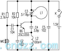
The loop antenna L1 is utilized for emission and also functions as the oscillation coil. The high-frequency current flowing through the antenna is synchronized in resonance with the oscillation frequency, ensuring optimal emission performance. Practical applications indicate that the...
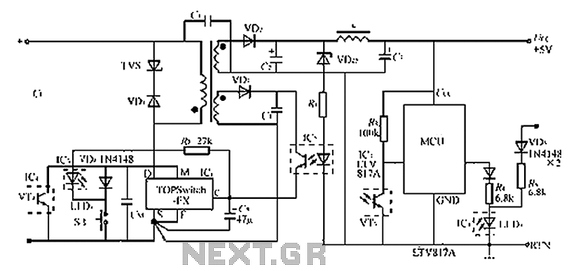
The circuit diagram of the TOPSwitch FZ chip switching power supply is controlled by microcontrollers (MCUs). The microcontroller can be utilized with inkjet printers, laser printers, and other computer peripherals. The TOPSwitch FX, which constitutes the switching power supply...