
high voltage low current supply circuit diagram
The high voltage power supply circuit is composed of several key components that work in conjunction to produce the desired output. The blocking oscillator utilizes a transistor, which serves as the primary switching element. The feedback mechanism is critical for maintaining oscillation, allowing the circuit to continuously generate high voltage until the supply is turned off.
The transformer plays a pivotal role in stepping up the voltage. It consists of a primary winding, a feedback winding, and a secondary winding. The primary winding receives the input voltage and, through electromagnetic induction, generates a high voltage in the secondary winding. The design of the transformer, including the number of turns in each winding, is crucial for achieving the required voltage step-up ratio.
The Cockcroft-Walton circuit, employed as a voltage multiplier, consists of a series of capacitors and diodes arranged in a specific configuration to convert the AC voltage from the transformer into a higher DC voltage. Each stage of the multiplier increases the voltage in a stepwise manner, resulting in the final output of approximately 2 kV.
Safety considerations are paramount when working with high voltage circuits. Proper insulation, component ratings, and circuit protection measures must be implemented to prevent electrical shock and equipment damage. Regular testing and maintenance are recommended to ensure the reliability and safety of the power supply. Overall, this high voltage power supply circuit is a versatile solution for applications requiring high voltage with relatively low current.Ahigh voltage power supply is a very useful source which can be effectively used in many applications like biasing of gas-discharge tubes and radiation detectors etc. Such a power supply could also be used for protection of property by electric charging of fences. Here the current requirement is of the order of a few microamps. In such an applicat ion, high voltage would essentially exist between a live wire and ground. When this live wire is touched, the discharge occurs via body resistance and it gives a non-lethal but deterrent shock to an intruder. The circuit is built around a single transistorised blocking oscillator. An important element in this circuit is the transformer. It can be fabricated on easily available ferrite cores. Two E sections of the core are joined face-to-face after the enamelled copper wire wound on former is placed in it.
The details of the transformer windings are given in the Table. In this configuration, the primary winding and the feedback winding are arranged such that a sustaining oscillation is ensured once the supply is switched on. The waveform s duty cycle is asymmetrical, but it is not very important in this application. Please note that if the oscillations do not occur at the switch-on time, the transformer winding terminals of the feedback or the primary winding (but not both) should be reversed.
The primary oscillation amplitude is about 24V(p-p). This gets amplified with the large step-up ratio of the transformer and we get about 800V(p-p) across the secondary. A simple series voltage multiplier (known as Cockroft-Walton circuit) is used to boost up this voltage in steps to give a final DC of about 2 kV.
The output voltage, however, is not very well regulated. But if there is a constant load, the final voltage can be adjusted by varying the supply voltage. The present configuration gives 2 kV for an input DC voltage of 15 V. Though higher voltages could be achieved by increasing input supply, one word of caution is necessary: that the component ratings have to be kept in mind. If the ratings are exceeded then there will be electrical discharges and breakdowns, which will damage the device Disclaimer: All the information present on this site are for personal use only.
No commercial use is permitted without the prior permission from authors of this website. All content on this site is provided as is and without any guarantee on any kind, implied or otherwise. We cannot be held responsible for any errors, omissions, or damages arising out of use of information available on this web site.
The content in this site may contain COPYRIGHTED information and should not be reproduced in any way without prior permission from the authors. 🔗 External reference
Related Circuits

This simple temperature relay circuit can be used to signal a fire or setpoint for temperature monitoring function. You need to adjust P1 so that T1's base. The temperature relay circuit operates by monitoring the temperature in a designated area...
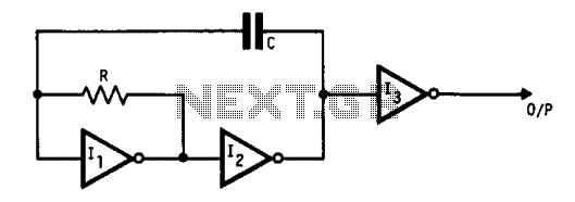
This oscillator utilizes standard inverters, one resistor, and one capacitor, and it does not have a minimum operating frequency. The resistor (R) and capacitor (C) must be selected to ensure that the currents flowing into the gates remain below...
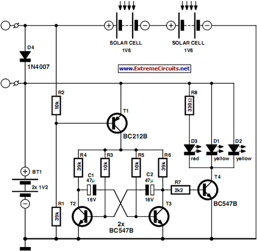
This circuit is designed as a warning flasher to alert road users to dangerous situations in low-light conditions. It can also function as a bicycle light, adhering to traffic regulations. White LEDs are recommended for use as a front...
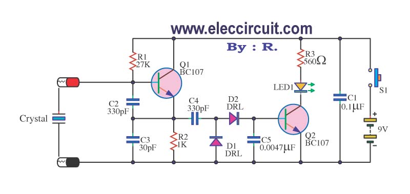
A multimeter cannot be used to test a crystal oscillator. Instead, a dedicated circuit is required, capable of checking crystals within the frequency range of 100 kHz to 900 MHz. This circuit is easy to construct and cost-effective. To construct...
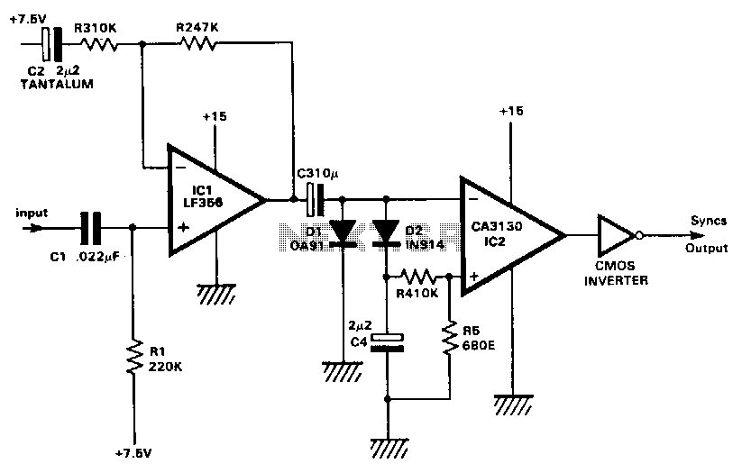
This circuit extracts the synchronization pulses from a video signal across a wide range of amplitudes and operates on a single +15 V supply. IC1 buffers and amplifies the incoming signal and applies it via C3 to the peak...
When the water level is below the steel rods, there is no contact between the metal can and the rods, which are supported by a small insulated wooden board. The small circuit built around IC1 does not draw any...