
Audio Stereo Amplifer

The stereo amplifier project emphasizes a modular approach, allowing for flexibility and adaptability in design. The custom-built enclosure will house the amplifier components, ensuring a neat and organized assembly. The inclusion of a VU meter not only enhances the functionality but also provides visual feedback on audio levels, contributing to a more interactive user experience.
The power supply unit plays a crucial role in the operation of the amplifier. The +5VSB standby rail ensures that critical components remain powered even when the amplifier is in a low-power state. The red LED serves as an essential indicator, signaling the connection to mains power, while the transition to green upon activation confirms the amplifier's operational status. The PWR_OK signal is integral to this process, ensuring that the system is ready for use.
The implementation of an H-bridge circuit for the bi-color LED adds versatility to the visual indicators on the amplifier. This configuration allows for dynamic signaling, where the LED color changes based on the amplifier's state, providing immediate visual cues to the user.
The volume control will be achieved using a logarithmic potentiometer, which is standard in audio applications due to its ability to provide a more natural response to human hearing. The integration of the Philips TDA1524 chip not only simplifies the volume control process but also introduces advanced features such as tone and balance control. This chip is well-regarded for its performance in audio applications, offering precise control over sound characteristics.
Overall, this project encompasses a comprehensive approach to building a stereo amplifier, focusing on modularity, functionality, and user experience. Detailed instructions for constructing the tone and balance control module based on the TDA1524 chip are essential for achieving the desired audio quality and performance.This setup is quite messy in terms of wires, so I`ve decided to remove both from their respective housings and place them in a nice, custom-built box. Right, so while I`m about to do that, aren`t there any other goodies toadd, like a VU meter and volume control Yes, which is what this project is about ” how to built a stereo amplifier from various components and parts.
Everything is modular, so the system components can easily be changed, upgraded, replaced or have new goodies added. The PSU provides us with a standby rail (+5VSB, purple wire), which is used to power circuits that require power input during the powered down state of the unit.
A red LED, powered through this rail, will indicate that the unit is plugged into the main power. This LED should then turn to green when the unit is actually switched on. For this function we must use the PWR_OK (+5V, gray wire) signal. Two interesting aspects of the required circuit are that we can use an H-bridge to switch the polarity applied to a bi-colour LED and that the switch for the H-bridge needs to be of a special configuration. I would like this amplifier to have a volume control. This can easily be achieved with a logarithmic potentiometer on the input, but by using a circuit based on the Philips TDA1524 chip I also get tone (bass & treble) and balance control.
Details on how to build this module can be found here. 🔗 External reference
Related Circuits
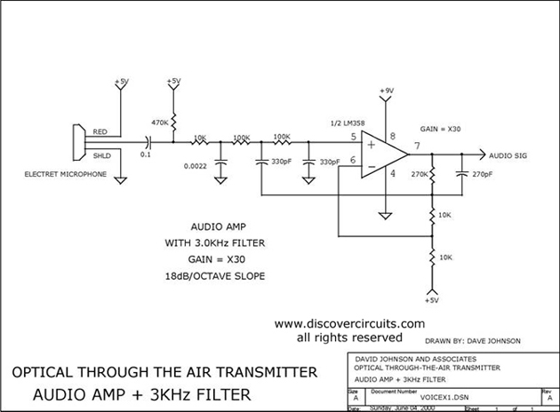
Audio amplifier with a 3 kHz filter. This circuit serves as the audio amplification section for a complete optical transmitter. It amplifies and filters voice audio signals from an electret microphone. The audio amplifier circuit is designed to enhance the...
This is a 25 Watt basic power amplifier designed to be relatively easy to build at a reasonable cost. It offers better performance than the standard STK module amplifiers commonly used in nearly all mass-market stereo receivers manufactured today. The...
The primary component of this three-band graphic equalizer is the LM833, manufactured by National Semiconductor. The LM833 features very low noise levels and operates with a bandwidth of 15 MHz. The LM833 operational amplifier is designed to provide high-performance audio...
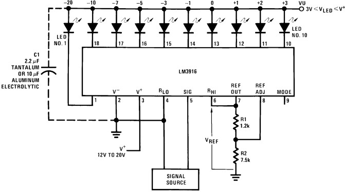
Convert the LEDs into LED bar graphs that display intensity. For instance, a song with a strong bass should cause the bar graph to rise to the maximum. The segments of the LED bar graph should consist of individual...
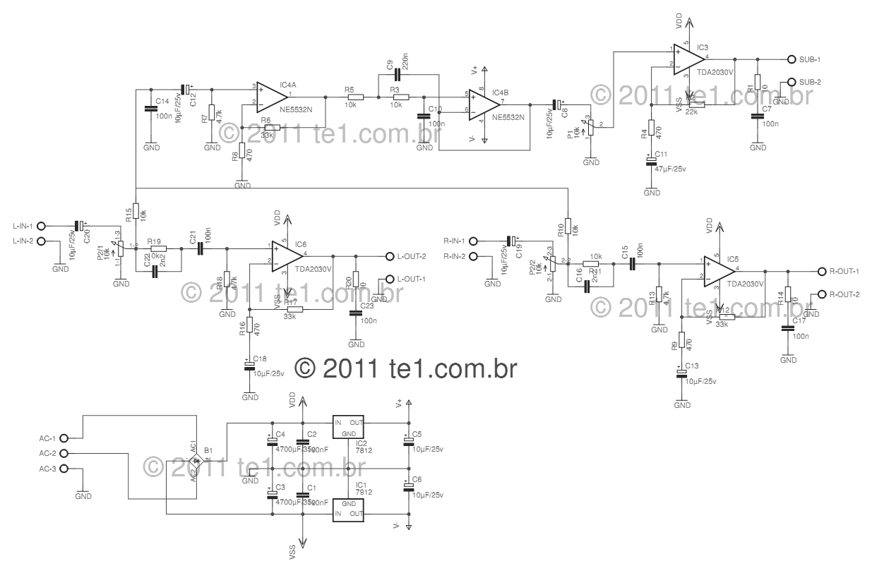
This circuit is a complete application for a 2.1 amplifier system, featuring two satellite speakers for TDA and one subwoofer. It is commonly used in commercial applications to enhance the audio output of computers using a stereo amplifier along...
The integrated circuit LM386 is a low-power audio frequency amplifier that requires a low-level power supply, typically batteries. It is available in an 8-pin mini-DIP package. The IC is designed to provide a voltage amplification of 20 without the...