
Audio Tone Control

The audio tone control circuit described employs a combination of passive and active components to achieve frequency response manipulation. The primary function of the tone control is to adjust the bass and treble levels of the audio signal to suit user preferences or to compensate for deficiencies in the listening environment. The use of a single potentiometer for both bass and treble adjustments simplifies user interaction while maintaining functionality.
In the schematic, the potentiometers R2 and R6 are configured to allow simultaneous adjustment of bass and treble frequencies. This dual control mechanism is beneficial in compact audio systems where space is a premium. The RC filter network, consisting of a resistor and capacitor, is designed to attenuate specific frequency ranges, allowing for the desired tonal shaping.
The implementation of a three-position switch adds versatility to the tone control by providing different capacitor values for selection, which alters the circuit's frequency response characteristics. This feature allows users to tailor the audio output to their specific listening preferences or adapt to different audio sources.
The operational amplifier (LM301) plays a critical role in the active portion of the circuit. It amplifies the signal while also providing feedback through the additional 10k resistor, which helps stabilize the gain and improve linearity. The configuration ensures that the tone adjustments made at the potentiometers are effectively translated into the output signal.
The design also highlights the importance of component values in achieving the desired performance. The inclusion of a 68k resistor to ground at the positive input of the operational amplifier is crucial for maintaining the bias point, ensuring that the amplifier operates within its optimal range.
Overall, the circuit serves as an effective solution for audio tone control, balancing simplicity and functionality, and providing a user-friendly interface for audio signal adjustment. The additional discussion on equalizer circuits signifies the broader context of tone control within audio engineering, emphasizing the importance of frequency management in sound reproduction.An audio tone control combines both a Base control and a treble control in the same circuit. Tone controls are found on lower-end audio gear because it saves both front panel space on the unit and only requires one control knob, instead of two separate controls. In this case potentiometers R2 and R6 are coupled within the same potentiometer case, so adjusting one also adjusts the other [one knob, but having separate resistive wipers [ Rotary Wafer Definition ]. The tone control to the right just uses a simple RC filter network, with the capacitor connected in parallel with the variable resistor.
The tone control circuit directly below uses a three position switch to select a different capacitor to change the tone of the signal, and is only slightly more complicated than just using a resistor trimmer. The circuit could be made with even fewer parts by only using one capacitor and a switch that connects it to the circuit or removes the capacitor, saving two capacitors.
Although the circuit to the right is not a Tone control, it is related to a Tone circuit. A Tone control would only consist of a single control or knob, but the circuit shown uses three separate variable resistors. However what is not depicted in the graphic is that those resistors could be ganged into a single package, basically producing a tone control.
The circuit is not a true tone control, but serves to show another circuit, or filter style used to control different frequency ranges. This design uses an LM301 operational amplifier to control the circuit. The passive portion of the tone control is almost identical to the first circuit shown at the top of the page.
However there is an additional 10k resistor added between the potentiometer and the Op Amp. Note also that resistor R3 and capacitor C4 are also no longer returned to ground, but now form part of the feedback circuit. Resistor R4 and R5 has also been combined into a signal resistor, which is now connected to the trimmer.
The output of the passive circuit is now applied to the negative input of the Op Amp. The plus input of the amplifier is taken to ground via a 68k resistor, which is only used to compensate for bias currents. Note that this example circuit also provides component values for a typical tone control. This next topic concerns Equalizer Circuits, which are really just single-band tone controls, or use the links just to the right for more complicated 2 and 3-band tone controls.
🔗 External reference
Related Circuits
This circuit below shows a teleremote circuit that enables the switching on and off of appliances through telephone lines. The teleremote circuit utilizes a telephone line as a medium for controlling electrical appliances from a distance. The primary components...
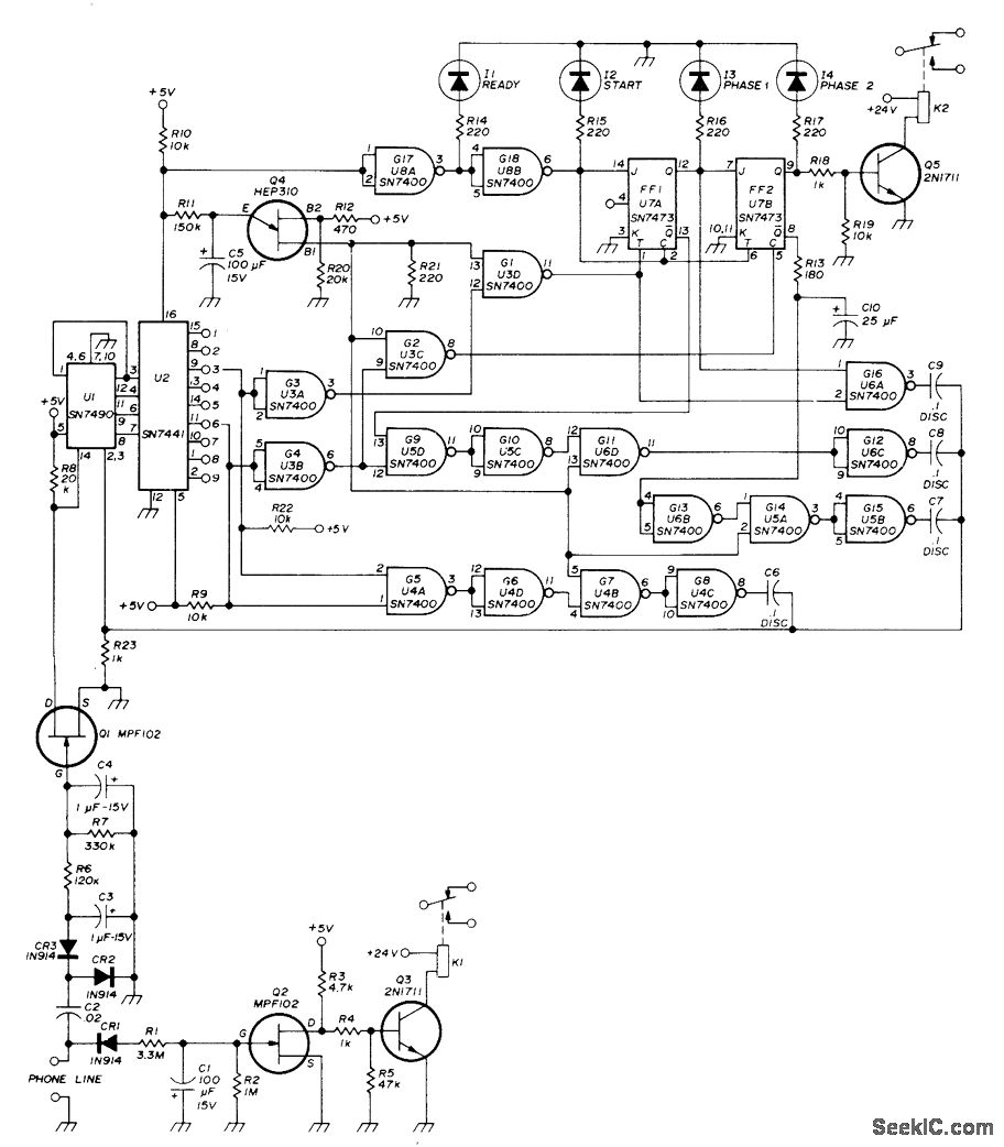
A repeater or other unattended equipment can be activated or deactivated using a standard telephone. The process involves calling the remote station, allowing it to ring three times, hanging up, waiting for 20 seconds, redialing the number, and letting...
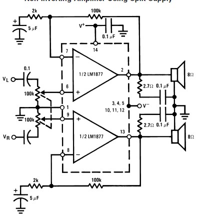
This audio amplifier circuit is designed to deliver 2W per channel continuously into 8-ohm loads. The LM1877 is engineered to function with a minimal number of external components while still offering flexibility for applications in stereo phonographs, tape recorders,...
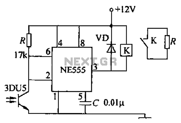
A transmitting circuit powered by an infrared light-emitting diode emits light. The receiving circuit, shown in the figure, utilizes a transistor (3DU5) to receive the infrared light and output the received signal. The signal is sent to terminal 3...
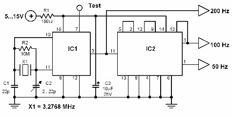
This circuit generates a 50 Hz timebase signal that is independent of the power line frequency. It is designed to provide the 50 Hz signal for electronic circuits that operate specifically with this clock frequency, primarily for circuits and...
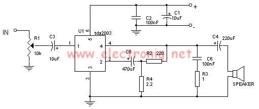
The TDA2003 audio amplifier integrated circuit can be used to design a straightforward 10-watt power audio amplifier for a 2-ohm load or 4 watts for a 4-ohm load. The TDA2003 offers high output current capacity (up to 3.5A) and...