
3170 IC For Telephone Remote Control Circuit

The teleremote circuit utilizes a telephone line as a medium for controlling electrical appliances from a distance. The primary components of this circuit include a telephone interface, a relay module, and the appliance to be controlled.
When a user makes a call to the designated telephone number associated with the teleremote circuit, the circuit detects the incoming call through the telephone interface. This is typically achieved using a hook switch or a dedicated telephone line interface IC. Upon detecting the call, the circuit may generate a signal to activate a relay, which is connected to the appliance.
The relay acts as a switch that can handle the high voltage and current required by household appliances. Depending on the design, the circuit may allow for toggling the state of the relay with either a single call or by detecting specific tones or DTMF (Dual-Tone Multi-Frequency) signals.
For enhanced functionality, the circuit can be designed to provide feedback to the user, such as an audible tone or a visual indicator (LED) to confirm that the appliance has been successfully turned on or off. Additionally, safety features may be incorporated to prevent unauthorized access or accidental activation of the appliance.
This type of circuit is particularly useful in home automation systems, allowing users to control appliances remotely without the need for specialized equipment beyond a standard telephone. The simplicity of utilizing existing telephone infrastructure makes it a cost-effective solution for remote control applications.This circuit bellow shows a teleremote circuit which enables switching ‘on and ‘off of appliances through telephone lines. Can be used .. 🔗 External reference
Related Circuits
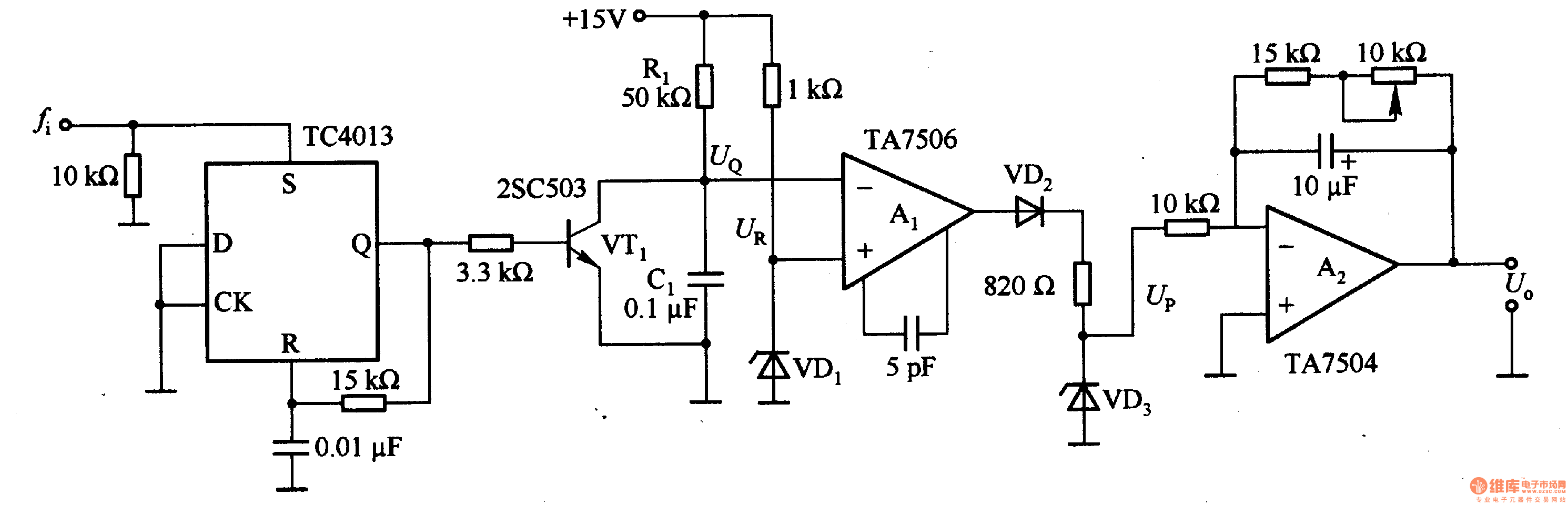
This circuit can convert an input frequency ranging from 0 to 100 Hz into an output voltage of 0 to 10 V. It utilizes the TC4013 monostable multivibrator to shape and amplify the input pulse, which has a width...

This Project REMOTE CONTROLLED SWITCH BOARD is used to switch on/off the Home Appliances by using a standard Remote control. The system is used to switch on/off up to six electrical devices. All the above processes are controlled by...
This compact amplifier is built around the TDA2003 integrated circuit, which can deliver 4W RMS at a 4-ohm load. The TDA2003 offers enhanced performance while maintaining the same pin configuration as the TDA2002. It retains the advantageous features of...

The pressure transmitter circuit data acquisition system utilizes the 1B31, an 18-bit A/D converter (AD1170), and an MCS-51 microcontroller. The configuration, as depicted in the accompanying diagram, features a full-scale output voltage of 10 mV from the pressure transmitter...
Motor Bike Headlight Controller Circuit. This circuit automatically turns a motorcycle's headlight on and off, independently of both the light and ignition switches, provided the battery is fully charged. The first stage... The motorcycle headlight controller circuit is designed to...
Beeper and/or LED remotely-operated via mains supply line. Pressing the pushbutton of the transmitter, a sound and/or light alert is activated in the receiver. The system uses no wiring or radio frequencies: the transmitted signal is conveyed into the...