
audio-video modulator circuit

The circuit designed for converting audio and video signals into a UHF TV signal serves a crucial function in enabling the connection of various video sources, such as cameras, to standard television sets. The use of the LH0032 operational amplifier in the video amplifier circuit ensures high-speed processing of the signals, which is essential for maintaining signal integrity and quality during transmission.
The components listed in the parts list are selected to optimize performance and reliability. Resistors R1 through R15 provide necessary impedance matching and signal conditioning, while capacitors C1 to C4 are employed for coupling and filtering purposes. The choice of a 10µF capacitor for C1 aids in blocking DC components while allowing AC signals to pass through, ensuring that only the desired audio and video signals are amplified.
In the laser communication system, the modulation of the laser beam's intensity in accordance with the audio signal enables wireless transmission of sound. This method is advantageous for applications requiring secure and interference-free communication. The conversion of laser intensity variations into voltage changes is critical for accurate signal reception.
The Active Tone Control circuit, or ACTOR, utilizes the Baxandall tone control system to enhance audio playback quality. By actively boosting bass and treble frequencies, this circuit allows users to customize their audio experience, making it suitable for various listening environments and preferences.
The UHF band TV antenna booster circuit is designed to improve the reception of UHF signals, particularly in areas with weak signal strength. The band-pass filter formed by the specified components ensures that only the desired frequency range is amplified, while unwanted signals are attenuated. This results in clearer and more reliable television reception.
Lastly, the turbo bass circuit effectively enhances low-frequency audio signals, making it an excellent addition to audio systems that require improved bass response. The use of operational amplifiers in this design allows for precise control over the amplification process, ensuring that the output maintains fidelity to the original audio source. Overall, these circuits represent a diverse range of applications in audio and video signal processing, showcasing the versatility and effectiveness of modern electronic design.The circuit will convert an audio and video signal into a UHF TV signal. It`s desired to connect a video signal originating from a camera or other video source to a normal TV set. The audio and video signal is converted into a UHF TV signal so. This is schematic diagram of a video amplifier ci rcuit, built based very high speed opamp IC LH0032. Parts List: R1 = 15K ©+15K © R2-3-4 = 10K © R5, R6, R7, R8, R9 = 1K © R10 = 820 © R11 = 1M © R12 = 100 © trimmer R13, R14, R15 = 47 © R14 = 10K © C1 = 10uF 63V MKT C2, C3, C4 = 100nF/63V C3 = 4. 7pF. This is the circuit diagram of laser communication system that transmit the sound or music signals by way of a laser beam.
The intensity of the laser beam varies together with the amplitude of the sound signal. The variation within the intensity of the laser beam is converted into a variation in the voltage level. The following diagram is the schematic diagram of Active Tone Control circuit, or we often call thic circuit as "ACTOR" Active Tone Control or ACTOR is a electronic audio circuit that serves to increase the Loudness (Bass and Treble audio signal) is active because it uses the Baxandall system.
This circuit does not use a. This is the circuit diagram of UHF band TV antenna booster with 15dB gain power. This low cost antenna booster is simple and easy to build. This circuit formed based on BF180 UHF Transistor. The first stage is an band pass filter constructed by the C1, CV1, L1, L4, C7 and C3, the second stage. This circuit is a circuit of the turbo bass that can be used to multiply the low frequency sound signals (bass) on your audio system.
This circuit is an active circuit in which the incoming audio signal from the input will be strengthened in the first op-amp. The second op-amp that will filter out the. 🔗 External reference
Related Circuits
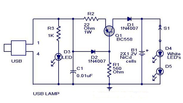
A simple USB-powered lamp designed to illuminate a desktop during power outages. The circuit operates at 5 volts sourced from a USB port. The 5V from the USB is directed through a current-limiting resistor (R2) and a transistor (Q1)....
This circuit utilizes a relay to control a water pump, enabling automatic level management of a water reservoir or well. The shorter steel rod functions as the "water high" sensor, while the longer rod serves as the "water low"...
U1 is the 3817 integrated circuit, capable of directly driving the display. It can show time in either 12-hour or 24-hour format, schedule alarm sounds, and automatically turn on the radio at specified times. The display utilizes the FND500...
There are two independent modeling light circuits for the P2000D, one for each of the two channels. The modeling light circuit is completely separate from the high voltage strobe circuitry, even featuring its own On/Off switch. Therefore, the functionality...

The micro ampere meter presented here functions as a DC millivolt meter. It achieves full-scale deflection with a 0.1V input. The current to be measured flows through a known resistance R, and the voltage drop across this resistance is...
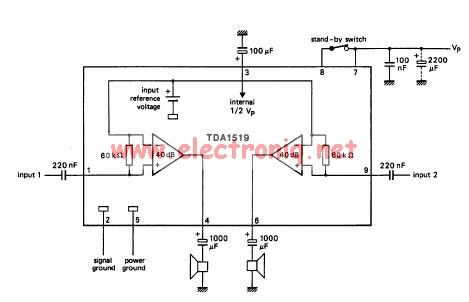
The TDA1519 circuit can deliver 2x6 watts of output power. The TDA1519 is an integrated class-B dual output amplifier housed in a 9-lead single in-line (SIL) plastic medium power package, primarily developed for car radio applications. The TDA1519 amplifier is...