
Norman P2000D Modeling Light Circuitry

The P2000D features dual independent modeling light circuits, each corresponding to its respective channel. This design allows for versatile lighting control without interference from the strobe circuitry, which operates at high voltage. Each modeling light circuit includes an On/Off switch, ensuring that users can operate the modeling lights independently of the strobe functionality, which is critical for troubleshooting and maintenance.
The top panel of the P2000D contains two potentiometers that allow for precise adjustment of the modeling light power levels. These potentiometers are connected to a dedicated circuit board located within the upper section of the device. This circuit board employs a TRIAC dimmer, which is a solid-state device known for its ability to control power flow and adjust the brightness of incandescent lamps. The TRIAC is controlled by the potentiometers, enabling smooth dimming of the modeling lights.
The output from the TRIAC dimmer is routed through a grey wire to Pin F on the strobe lamp connectors, while the return path for power is established via Pin E. This configuration ensures that the modeling lights receive the appropriate voltage and current levels for optimal performance. The schematic for the control board has been carefully traced to facilitate any necessary repairs in the future, although specific component values, such as the trim pot, were not documented.
As the project progressed, the acquisition of a Norman TriLite provided an opportunity to further explore the high voltage circuitry associated with the strobe operation. The absence of a transformer capable of stepping up the mains voltage indicates that a voltage multiplier is likely in use. A 3X voltage multiplier would provide the necessary voltage levels for strobe operation, as a 2X multiplier would fall short of the required specifications. This understanding of both the modeling light and strobe circuits is essential for effective troubleshooting and repair of the P2000D lighting system.There are two independent modeling light circuits for the P2000D - one for each of the two channels. The modeling light circuit is completely independent from the high voltage strobe circuitry - to the point of having its own On/Off switch. This means, of course, that just because the modeling lights are working your strobe circuits can be fried.
Be careful if someone sells you a pack and says - well I can`t test the strobe but the modeling lights are working. There are two modeling light power level potientiometers on the top panel. These lead to a small circuit board in the top half of the pack. This circuit board uses a fairly simple TRIAC dimmer to control the intensity of the lamps. The output from this board runs via a grey wire to Pin F on the strobe lamp connectors. Return power goes via pin E. I traced out the schematic of the control board as best I could. I did not attempt to measure the value of trim pot and could not identify the DIAC (though I pretty much am sure that it is a DIAC based on other dimmer schematics.
) I then sketched out the basic layout and circuit traces in case I needed to repair this circuit in the future. You can see it below (not entirely to scale ) A quick sidebar - When I started the project I had no strobe head.
However I just acquired a Norman TriLite (this is a projector lamp and strobe light in a spotlight type assembly) [more] So now that I warmed up with the modeling light circuit, it is time to start sketching out the high voltage circuitry use for the strobes. As I saw no transformer large enough to be used to step up the mains voltage, I knew that a voltage multiplier must be used.
A 2X multiplier would not produce enough voltage but a 3X mutliplier should. 🔗 External reference
Related Circuits
Since the circuit operates at greater than mains potential and is not isolated by a transformer, it is extremely dangerous. The DC operating potential is about 340V, and there is more than enough stored charge to kill you many...
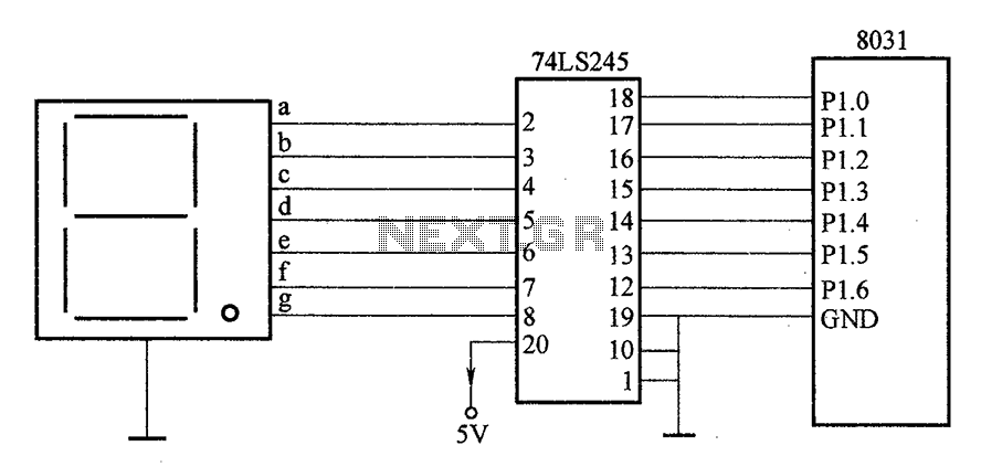
After the SCM execution, the Pl output port connects to the bidirectional input of 74LS245 driver chips. This driver operates during each phase of digital control, based on the information from the Pl port. The purpose is to convert...
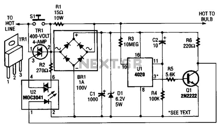
The automatic porch-light control circuit maintains a triac in an active state until a 4020 divider counts a series of 60-Hz power line pulses. This circuit is designed to turn off the light after a specified duration, utilizing pins...
A general-purpose hobby circuit for a simple light fence security beeper is presented here. This circuit can be utilized as a door alarm, gate alarm, pathway alarm, and more. It can be powered by any 12 Volt DC power...
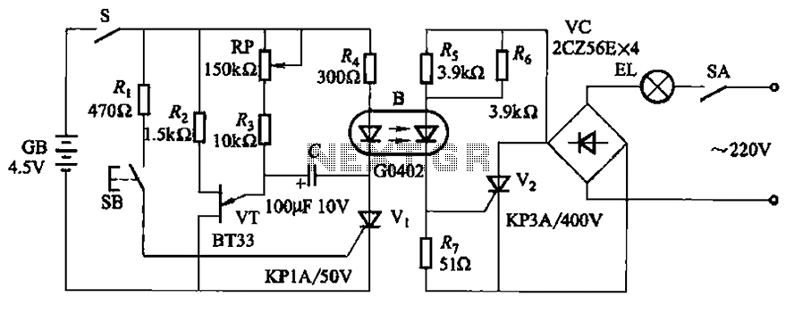
The circuit illustrated in Figure 2-48 consists of two configurations. Configuration 2-48 (a) operates using a 4.5V battery, while configuration 2-48 (b) employs AC capacitors to reduce the voltage supply. In configuration 2-48 (a), the delay time is influenced...
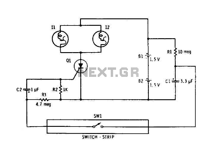
Capacitor C1 is connected continuously through a supply of 3 volts to a 10 megohm resistor R1. The capacitor charges relatively slowly to 3 volts. When switch SW1 is closed, it connects the charged capacitor C1 in series with...