
Audio Voice-Over Circuit using LM380

The microphone preamp circuit is essential in applications where clear voice communication is critical, such as in intercom systems, public address systems, and two-way radios. The circuit typically consists of a microphone, an operational amplifier (op-amp), resistors, capacitors, and a push-to-talk (PTT) switch.
In operation, the microphone captures sound waves and converts them into an electrical signal. This weak signal is then fed into the op-amp, which amplifies it to a usable level. The change-over switch allows the user to select between the microphone input and other audio sources. When the PTT switch is pressed, it activates the microphone circuit, ensuring that the voice signal is prioritized and clearly transmitted over any background audio.
The design may include additional components such as low-pass filters to eliminate high-frequency noise and ensure a clean audio output. Furthermore, careful consideration must be given to the power supply requirements of the op-amp to maintain optimal performance. Overall, this microphone preamp circuit is a vital component in achieving effective voice communication in various electronic systems.This circuit is a circuit diagram of a microphone preamp and circuits (voice circuit) has priority over any other audio signal. In its simplest form, the voice-over only the microphone unit and the change-over switch eating an amplifier, the output of the microphone has priority over the amplifiers audio signal when the push-to-talk switch is pressed
🔗 External reference
Related Circuits
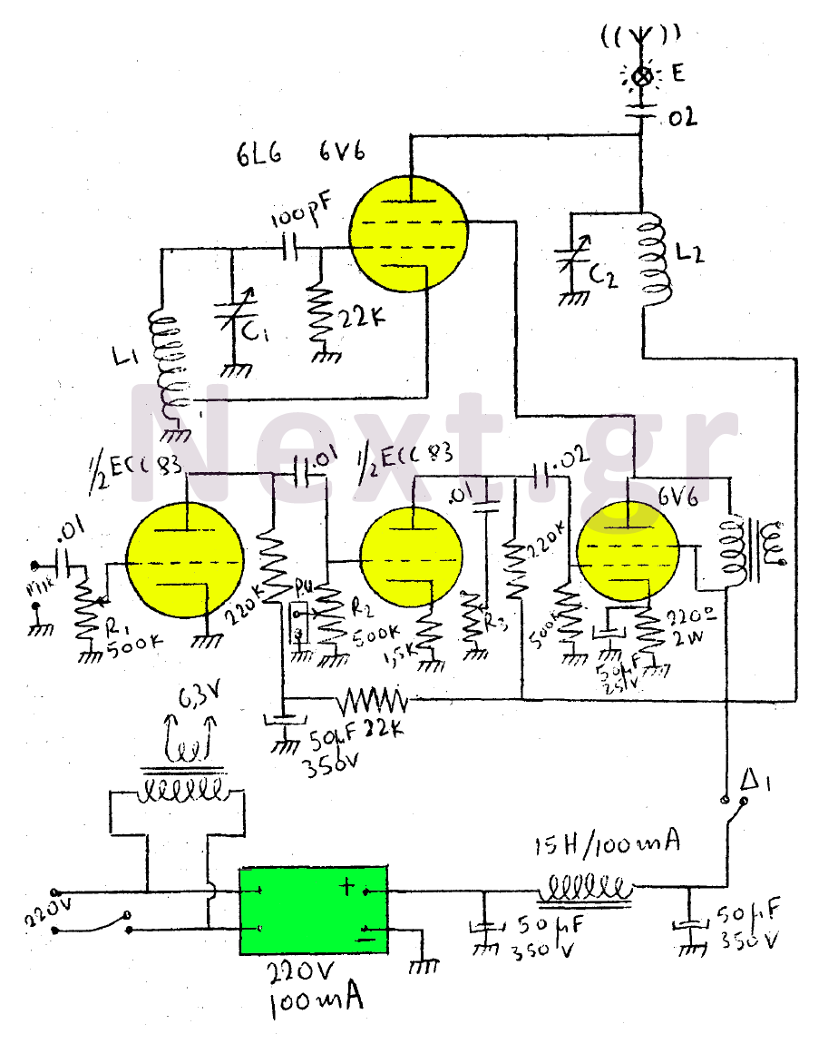
This circuit features a wearer assembly that includes a single lamp, either a 6V6 or 6L6, functioning as both an oscillator and an output amplifier. Coil L1 serves as the medium wave oscillation coil, while coil L2 is composed...
This simple circuit indicates the amount of power delivered to a loudspeaker. The dual-color LED displays green at an applied power level of approximately 1 watt. At 1.5 watts, it glows orange, and above 3 watts, it shines bright...
The circuit diagram represents a simple parking sensor system that measures the distance between the rear bumper of a vehicle and obstacles located behind it. The schematic consists of two main components: the transmitter and the receiver. The distance...
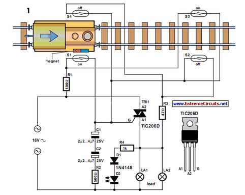
Modern electronics is essential for every large model railroad system, providing solutions to nearly every issue. Although ready-made products are available... Modern model railroad systems rely heavily on advanced electronics to enhance functionality and user experience. These systems often incorporate...
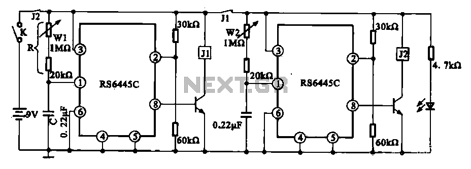
The timing integrated circuit (IC) RS6445C functions as a blocking oscillator. It features two segments, WI and W2, which are utilized to adjust the working time and the closure time. These adjustments can be continuously set within a range...
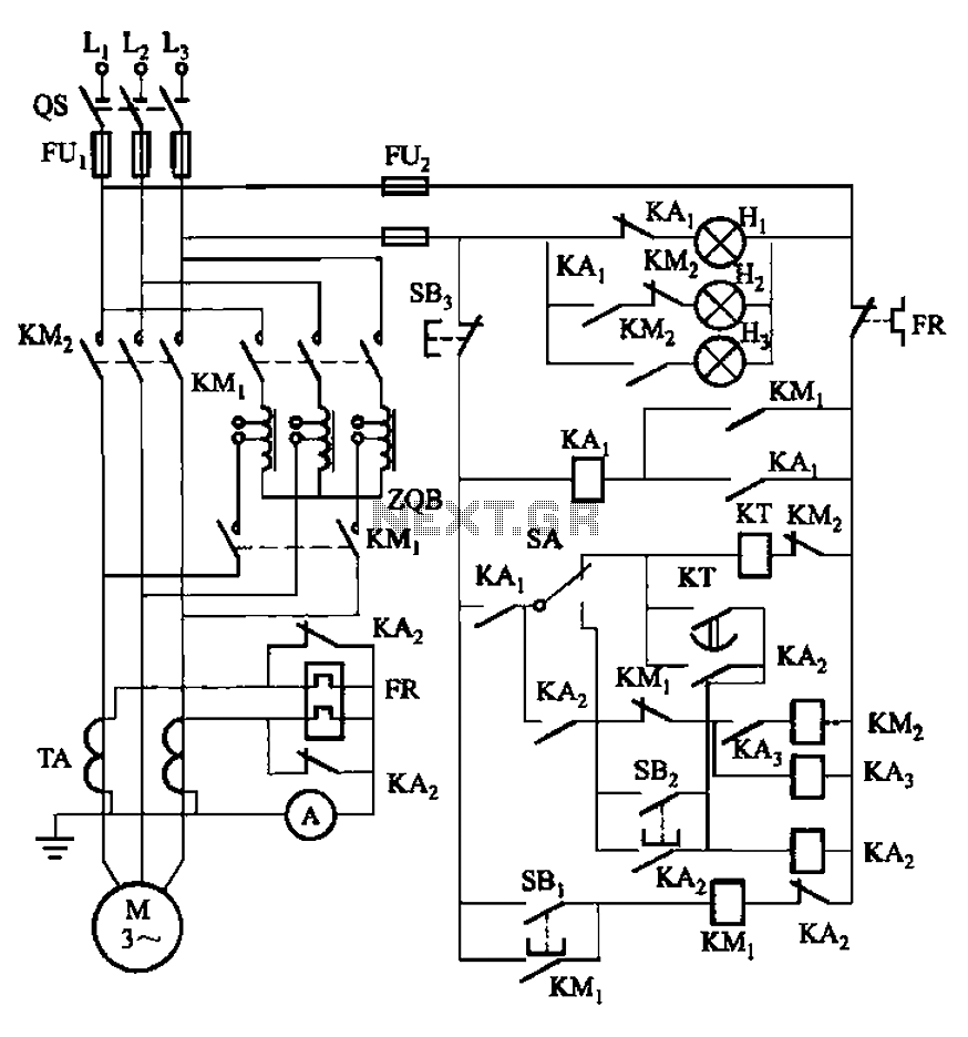
The circuit illustrated in Figure 3-56 features both manual and automatic start-up modes. It incorporates two relays, KA2 and KA3, within the control loop. The circuit design ensures that KM1 is cut off before and after activating KM2. A...