
Audio Power Meter

This circuit serves as a power indicator for audio amplifiers driving loudspeakers, utilizing a dual-color LED to visually represent the output power levels. The circuit is designed to operate in parallel with the loudspeaker, effectively monitoring the audio signal while introducing minimal additional load. The configuration incorporates a 470 Ohm resistor in parallel (R1//R3), ensuring that the load does not adversely affect the amplifier's performance.
The operation of the circuit hinges on the characteristics of the dual-color LED, which changes color based on the power levels detected. The green LED indicates a low power output (approximately 1 watt), transitioning to orange at 1.5 watts, and finally to red at power levels exceeding 3 watts. This color change is facilitated by the transistor T1, which is controlled by the voltage divider formed by resistors R2 and R1. As the output voltage increases during the positive half-cycle of the audio signal, T1 begins to conduct, causing the green LED to turn off and allowing the red LED to illuminate during the negative half-cycle.
The design allows for flexibility in adjusting the power thresholds by modifying the resistor values, accommodating different listening environments and amplifier specifications. The use of 0.25 W resistors is adequate for amplifiers with a maximum continuous output of 40 W. However, exceeding this power rating may lead to overheating or failure of the transistor. It is also important to note that the circuit's specifications are tailored for 4-ohm loudspeakers; adjustments must be made for use with 8-ohm speakers, specifically halving the resistor values to maintain accurate power indication.
In summary, this circuit provides an effective means of monitoring loudspeaker power levels in audio applications, combining simplicity with functionality while ensuring compatibility with a variety of amplifier configurations.This simple circuit indicates the amount of power that goes to a loudspeaker. The dual-color LED shows green at an applied power level of about 1 watt. At 1. 5 watts it glows orange and above 3 watts it is bright red. The circuit is connected in parallel with the loudspeaker connections and is powered from the audio signal. The additional load that this represents is 470 Ohm (R1//R3) will not be a problem for any amplifier. During the positive half cycle of the output signal the green LED in the dual-color LED will be turned on, provided the voltage is sufficiently high. At higher output voltages, T1 (depending on the voltage divider R2/R1) will begin to conduct and the green LED will go out.
During the negative half cycle the red LED is driven via R3 and will turn on when the voltage is high enough. In the transition region (where T1 conducts more and more and throttles` the green LED as a result) the combination of red/green gives the orange colour of the dual-LED.
By choosing appropriate values for the resistors the power levels can be adjusted to suit. The values selected here are for typical living room use. You will be surprised at how loud you have to turn your amplifier up before you get the LEDs to go! The resistors can be 0. 25 W types, provided the amplifier does not deliver more than 40 W continuously. Above this power the transistor will not be that happy either, so watch out for that too. Because T1 is used in saturation, the gain (Hfe) is not at all important and any similar type can be used. The power levels mentioned are valid for 4-Ohm speakers. For 8-Ohm speakers all the resistor values have to be divided by two. 🔗 External reference
Related Circuits
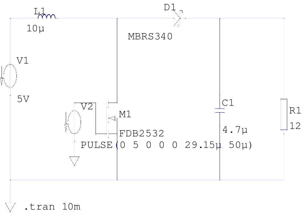
The supply voltage is 5V, and the goal is to increase it to 12V with a load current of 1A, resulting in an output power of 12W. A switching frequency of 20kHz has been selected, requiring a duty cycle...
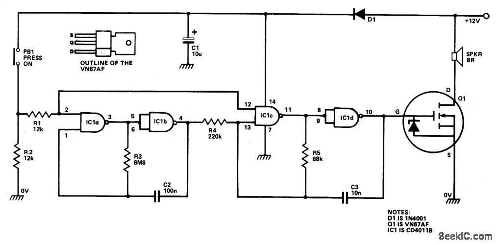
IC1a and IC1b are configured as a slow astable multivibrator, while IC1c and IC1d are set up as a fast astable multivibrator. Both configurations are of the "gated" type, allowing them to be activated or deactivated through push button...
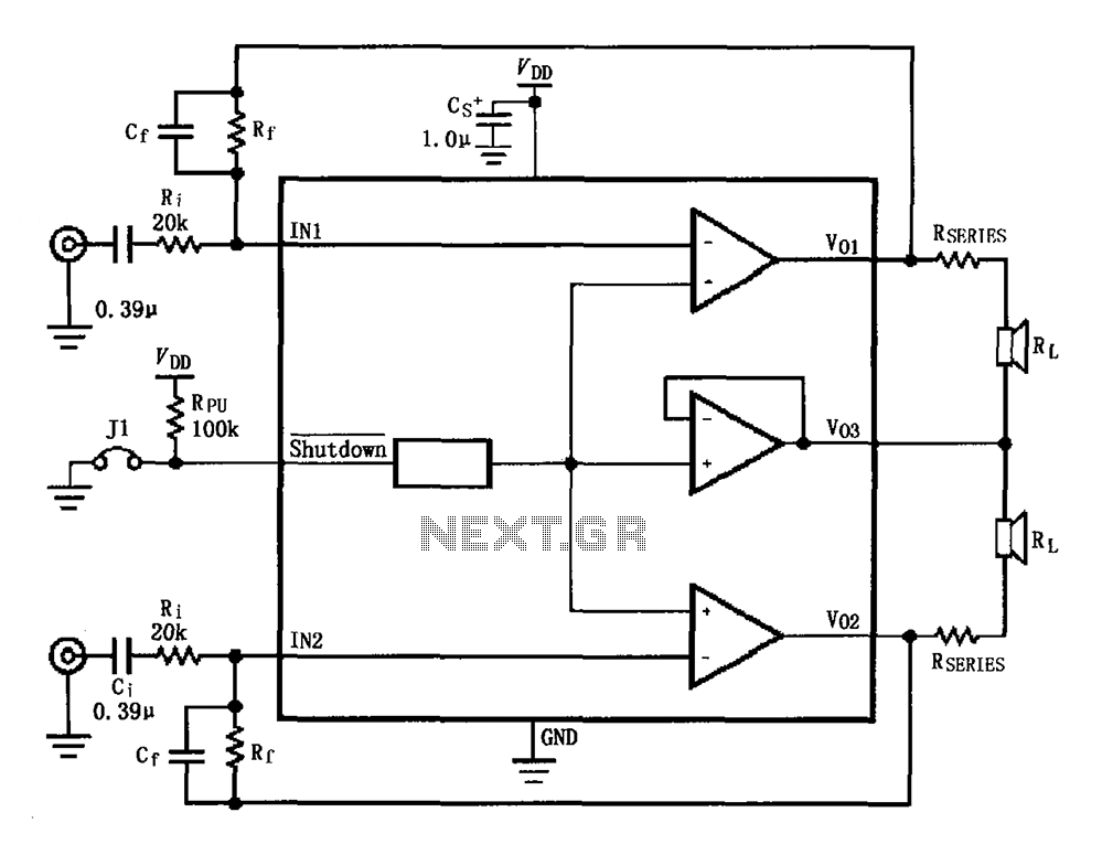
The circuit for the LM4910 is designed to minimize output noise and reduce power consumption. The output noise is attenuated by utilizing a resistor in series with the load. A feedback resistor Rf is used in conjunction with a...
T1 steps down AC voltage from 115VAC (or 220VAC) to about 8VAC and is then rectified via bridge rectifier BR1 to about 11.52Vdc. C1 filters off the AC ripple. If you find the circuit output too noisy add another...
The 7915 (at least the "made in Morocco" I used) needs a small load (some mA) to work correctly. If you get funny voltages (-18.4V or so), put a resistor from the 7915 output to ground (2k2 works good)....
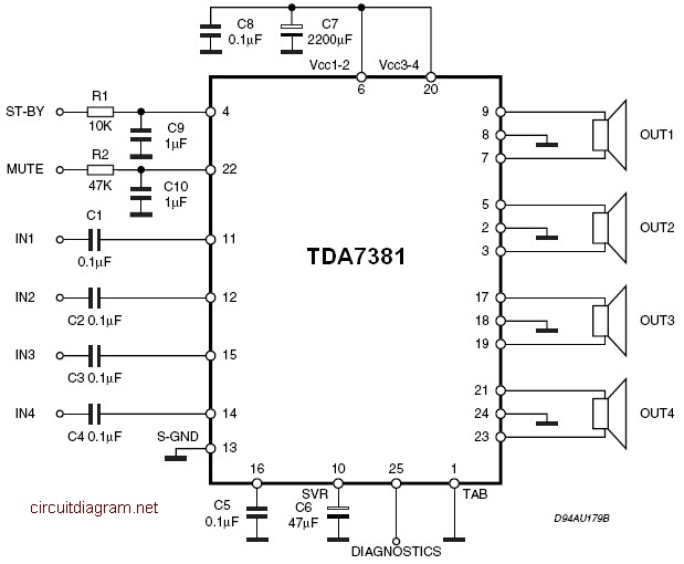
The amplifier is a quad amplifier circuit (amplifier with four inputs and four outputs) based on the TDA7381. This amplifier is designed for car audio systems, but it can also be utilized for other applications. The circuit has a...