
Audio Volume Control with Resistor Switches

The circuit design for a discrete resistor and relay-based audio attenuator typically incorporates a series of resistors arranged in a ladder network, with relays used to select the appropriate resistors for attenuation. Each relay corresponds to a specific resistor in the network, allowing for precise control over the audio signal level. The relay contacts are chosen for their low on-resistance and high durability to ensure minimal signal degradation.
In the schematic, the input audio signal is routed to a common point where it can be directed through the selected resistors based on the closed relays. The output is then taken from the junction of the selected resistors, which provides the attenuated audio signal. The configuration allows for 16 discrete volume levels, each defined by the combination of resistors selected. The use of a logarithmic taper is crucial in achieving the desired audio response, ensuring that the perceived loudness changes in a manner consistent with human hearing.
The impedance of the circuit is maintained around 100 kΩ, which is suitable for most audio applications. This impedance level helps to ensure compatibility with a wide range of audio sources and loads. The relay-based switching mechanism not only enhances the reliability of the audio path by reducing wear and tear associated with traditional potentiometers but also facilitates remote control capabilities, which can be particularly advantageous in complex audio systems.
Furthermore, the design can be easily expanded to accommodate multi-channel audio systems, where each channel can utilize its own set of resistors and relays, thereby maintaining signal integrity across multiple outputs. The careful selection of components, including high-quality resistors and relays, is essential to achieving the desired audio fidelity and performance, making this approach an attractive option for DIY audio enthusiasts seeking high-end sound quality.The traditional potentiometer is implemented with an electrical contact that slides over a resistive layer. An example of a well-known audio-grade potmeter is the Alps Blue. I still use this one myself. A high-end (good and costly) alternative is the rotary switch. This device consists of a series of discrete resistors and switches, of which always one switch is actually closed.
Resistor-switch networks can offer advantages over the potentiometer such as: Improved quality of the electrical contact, in comparison with the slider. Improved consistancy between separate audio channels (stereo or multi-channel). Less sensitive to dust and wear. Good audio attenuator rotary switches are made for instance by DACT. An impressive DIY rotary attenuator is here. It is special in using two decks of switches and two sets of resistors per channel. Nice switches and resistors are available for instance at www.triodes.nl. Of course there are integrated circuits that implement a similar functionality, and where the mechanical switches are replaced by MOSFETs. See for instance National and Cirrus. Clearly such devices allow nicely compact solutions. However, for truly high-end audio, I do not trust the sound quality of such devices due to the non-linear parasitic capacitances in such switches.
This page focusses on an alternative solution, using discrete resistors and relays as switches. While maintaining the advantages of the rotary switches, the relays offer improved options for remote control of the attenuation, and the solution becomes trivially extendible to handle multi-channel control. Furthermore, the use of small mass-produced relays promises great quality-for-money for DIY audio enthousiasts.
This is an example of such a project. A nice design is dicussed in this diyAudio thread. Circuit Examples and Properties Below, different circuits are presented. To obtain concise drawings and a fair comparison, all circuits are constructed to provide (just) 16 volume levels, with steps of 1.5dB, and with an impedance level of about 100Kohm. Remind that for audio volume control you want a logarithmic scale, that means that for every successive step the signal amplitude should be scaled by a constant factor, or in other words, every step scales the amplitude with a fixed number of dBs.
Such scaling gives a human impression of 'linear' sound level steps. (Note that the relay network in above link does not adhere to this property, but constant-voltage steps are made instead.) For characterization the following properties are shown: The number of resistors. The number of switches. The maximum number of closed switches in the signal path that carry audio current. The input and output impedance curves for varying volume. You might believe that, depending upon relay quality, the audio signal quality can degrade when passing through multiple (closed) contacts.
Open contacts normally have such high impedance (low capacitance) that they will not affect audio quality. Similarly, having many resistors (and solder joints) might affect quality. Of course, the number of restistors and switches has a cost implication. 🔗 External reference
Related Circuits
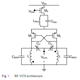
The oscillator is designed to tune from 1.8 GHz to 2 GHz for typical cellular telephony applications. An extended tuning range can be obtained by adjusting the ratio between the varactor capacitance and fixed capacitance in the tank. PMOSFETs...
In a lot of cars, the car radios use amplifiers that their output power does not exceed the 5W with enough distortion in the limits of power. The problem is tied with the utilization of external amplifiers, that will...
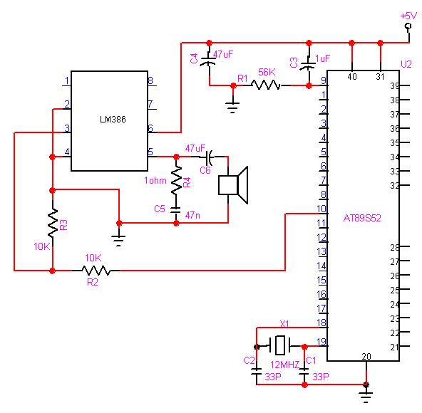
The 8051 microcontroller can play music tones. Here is a sample circuit and code that will play the music for "wishes you to be..." The 8051 microcontroller is a versatile and widely used microcontroller in embedded systems, capable of performing...
A more affordable method to create or purchase a device that offers similar functionality. It does not necessarily need to be remote-controlled if it can be programmed to activate at specific times. This description suggests the development of a cost-effective...
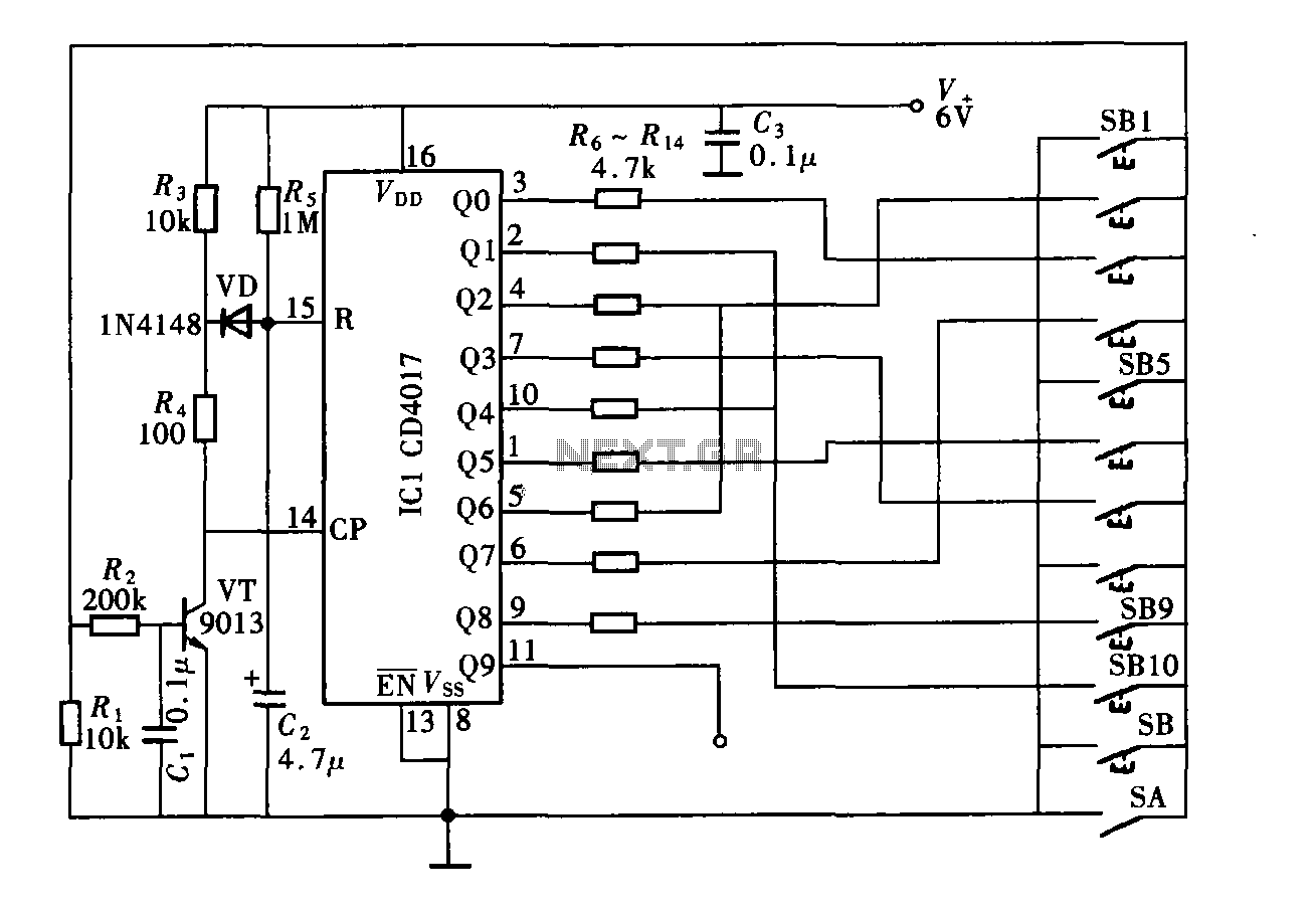
The digital controller features a nine-digit password system and includes a total of 11 keys. This comprises four pseudo-code keys and seven overlay keys, each of which has two valid key options. The total number of possible passwords is...
This works with a small geleidingstestertje LM 3909. It allows a tester beeps when the resistance between the probes between 0 and 100 ? lies. Due to the volume of the beep, the resistance between the probes can be...