
Battery monitoring instrumentation amplifier circuit diagram ISO120 and INA105 multiplexer 600V battery system

The circuit described is a sophisticated battery monitoring solution that effectively manages and safeguards a high-voltage battery system. The ISO120 serves as an isolation amplifier, providing electrical isolation between the high-voltage battery system and the monitoring circuitry. This is crucial for safety and protects sensitive components from high voltage. The resistor divider, composed of two 10kΩ resistors, reduces the 12V battery voltage to a manageable level (e/2) that can be safely processed by the ISO120.
The INA105 is an instrumentation amplifier that further processes the isolated signal. Configured with a gain of 1, it maintains the integrity of the voltage level while allowing for precise measurement. The output from the INA105 is then fed into a multiplexer, which can select different battery voltages for monitoring purposes. This multiplexer is essential for managing multiple inputs from the series-connected batteries, enabling the system to monitor each battery's state without requiring additional isolation amplifiers for each battery.
The overall design ensures that the battery monitoring circuit can effectively prevent conditions that may lead to overcharging or over-discharging, thereby extending the lifespan of the battery system and enhancing operational safety. This circuit is particularly valuable in applications where large battery banks are utilized, such as in renewable energy systems, electric vehicles, and industrial power storage solutions. By ISO120 and INA105 instrumentation amplifier as shown, multiplexer constituted 600V battery system battery monitoring circuit. This circuit 50 in series 12V battery (ie, the total voltage 600V) charging and discharging detection to prevent overcharging or over-discharging. ISO120 for a single input voltage across the battery terminal voltage 12V by two 10k resistor divider to obtain e/2 voltage, after the isolation amplifier to the INA105. INA105 inverting amplifier connected to a gain of 1, the output e/2 to the multiplexer, the multiplexer to select the output control.
Related Circuits
Do you have disco ears? If people ask you this and you are still well below 80, you may be experiencing hearing loss, which can result from prolonged exposure to loud music. The severity of the issue may not...
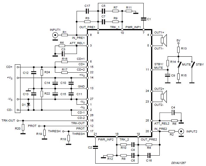
The Stereo Power Amplifier utilizes a 2x70Watt STA550 chip designed for audio power applications, featuring a BASH concept that allows connection to digital devices. This amplifier operates on a BTL (Bridge-Tied Load) system with a symmetrical power supply that...
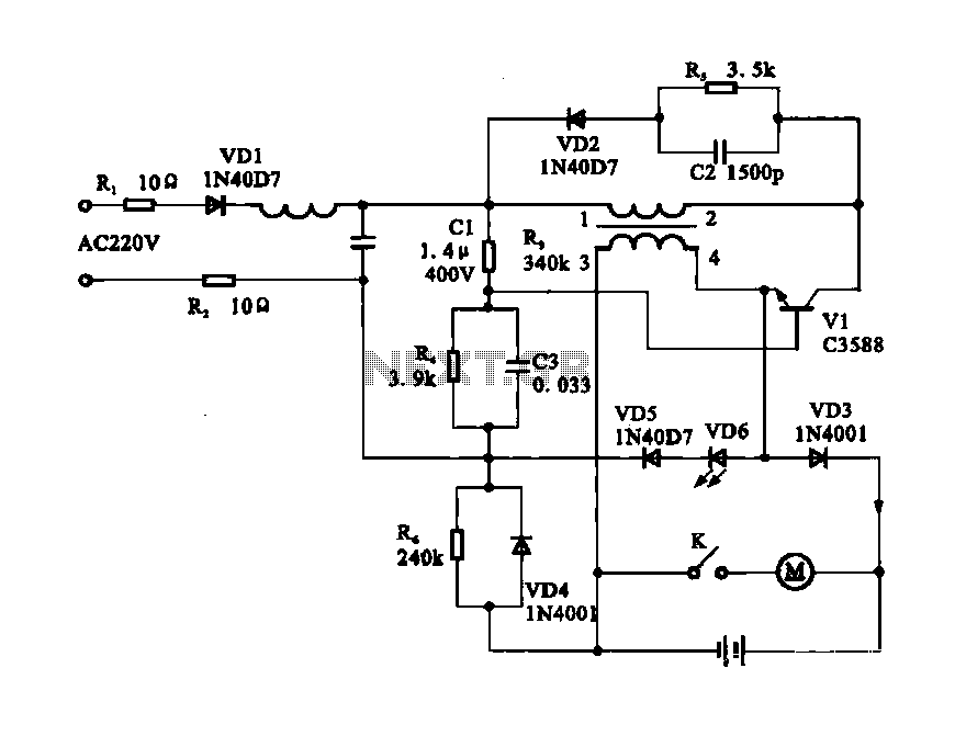
Electric shaver motor drive circuit. It illustrates a typical motor drive circuit for an electric shaver. AC 220V is used to charge the battery through the charging circuit, which also provides power to the motor. After activating the charge-on...
Many sites do not provide circuits for driving these transformers; they simply state that they are ineffective. However, this assertion is contested. A circuit has been developed that operates effectively, with significant effort invested in determining the resonant frequency...
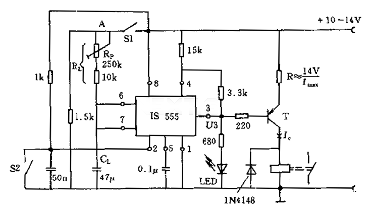
The circuit for the photoelectric switch S1 functions as a control switch for the luggage room light. In its closed operating state, the voltage is positive. If S2 is closed, irrespective of the state of S1, the output terminal...
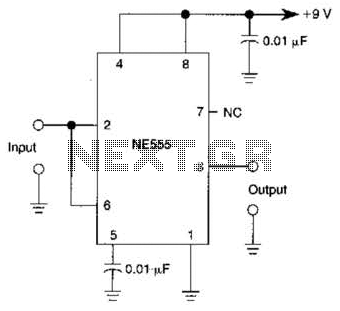
A 555 IC is configured to function as a Schmitt trigger. Inputs above and below the threshold level will turn the circuit on and off, producing a square wave output. The 555 timer integrated circuit (IC) is a versatile device...