
Electric shaver motor drive circuit

The electric shaver motor drive circuit is designed to efficiently manage the charging and operation of the motor using an AC voltage of 220V. The circuit typically includes a rectifier to convert the AC input into a DC voltage suitable for battery charging. This rectified voltage is then regulated to ensure that the battery receives a stable and appropriate charging current, preventing overcharging and extending battery life.
The inclusion of a charge-on switch (K) allows the user to control the activation of the motor. When the switch is closed, it completes the circuit, enabling the power supply to the motor. The motor is often equipped with a controller or driver circuit to manage its speed and torque, ensuring optimal performance during operation.
Additional components may include fuses for overcurrent protection, capacitors for filtering and smoothing the power supply, and diodes for preventing back EMF generated by the motor from damaging the circuit. The design may also incorporate a thermal cutoff switch to protect against overheating, ensuring safety during prolonged use.
Overall, this circuit design emphasizes reliability and user control, making it suitable for use in consumer electric shavers, where performance and safety are paramount.Electric shaver motor drive circuit It shows a typical motor drive circuit of an electric shaver. AC 220V to charge the battery through the charging circuit, but also for the m otor power supply. After the charge-on switch K, the motor can work.
Related Circuits
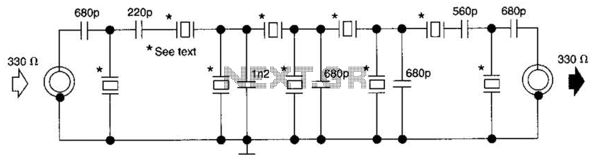
This filter utilizes five 455-kHz ceramic resonators. The impedance is 330 ohms, the bandwidth is 800 Hz, and the ultimate rejection is greater than 60 dB. Additionally, the ceramic resonators can be substituted with crystals. The described filter is a...
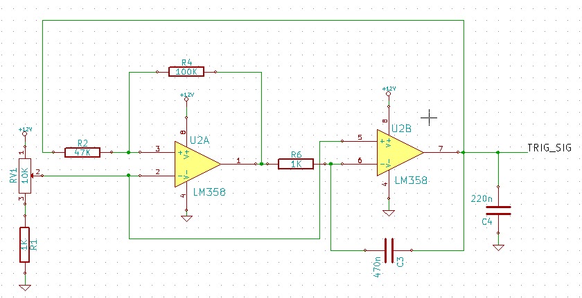
This circuit utilizes LM358 operational amplifiers (or any single supply operational amplifier) to generate a pulse-width modulated (PWM) signal. The design was specifically created for a local marine repair company that requested a circuit that is easily repairable and...
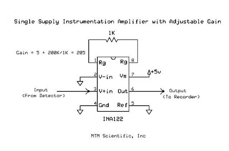
A common challenge for experimenters is increasing the gain of a low-level DC voltage for recording or analysis. Most instrumentation circuits require building a complicated project with dual power supplies and high-accuracy components. A simple solution is to use...
This is a very simple, low-cost, Hi-Fi quality power amplifier. It can be built in five different configurations, as shown in the table, ranging from 20 W to 80 W RMS. The Hi-Fi quality power amplifier circuit is designed to...
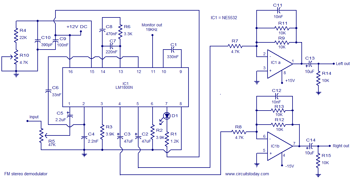
The following circuit illustrates the LM1800 IC Integrated FM Stereo Demodulator Circuit. Features include excellent sound quality and high-quality FM stereo. The LM1800 Integrated Circuit (IC) serves as a highly effective FM stereo demodulator, designed to deliver superior audio performance...

This circuit is designed to charge between one and twelve NiCd cells using a car battery. With switch S1 set to the normal position, it is capable of charging up to six cells. The circuit operates by utilizing a car...