
3 channel audio mixer (2N3904)
The described circuit functions as an audio mixer, designed to maintain a unity gain of one, ensuring that the output signal level matches the input signal level without amplification or attenuation. Each input channel is equipped with a 0.1 µF capacitor and a 100 kΩ resistor. The capacitor serves to block any DC offset in the audio signals, allowing only the AC audio signal to pass through to the subsequent stages of the mixer. The resistor, in conjunction with the capacitor, sets the output impedance of each input channel to 100 kΩ, which is a common impedance value that helps ensure compatibility with various audio equipment.
To accommodate multiple input channels, additional input paths can be created by replicating the existing configuration of one 0.1 µF capacitor and one 100 kΩ resistor for each new channel. This modular approach allows for flexibility in the design, enabling the mixer to handle multiple audio sources as needed.
The circuit is strategically positioned between the tone control circuitry and the power amplifier input. The output of the tone control circuit, which shapes the audio signal's frequency response, feeds into one of the mixer inputs. Other inputs may be configured either as grounded (for unused channels) or connected to other audio sources, allowing for seamless integration of various audio signals into the system.
This mixer configuration is particularly useful in audio applications where multiple sources need to be blended together before amplification, such as in home audio systems, musical instrument setups, or professional audio mixing environments. The straightforward design emphasizes ease of expansion and adaptability, making it suitable for a wide range of audio mixing tasks.That circuit will provide an overall gain of one between the output and each input channel. Each input channel includes a single 0.1uf capacitor and 100-Kilohms resistor to provide an output impedance of 100K. The number of input channels to this audio mixer can be increased by adding more capacitors and resistors with same value as capacitor(0.1uf) and resistor(100K).
The mixer should be located between the output of tone control circuitry and the input to the power amplifier. One input should be taken from the output of the tone control circuit, and the other inputs should either be grounded or taken from desired source. 🔗 External reference
Related Circuits
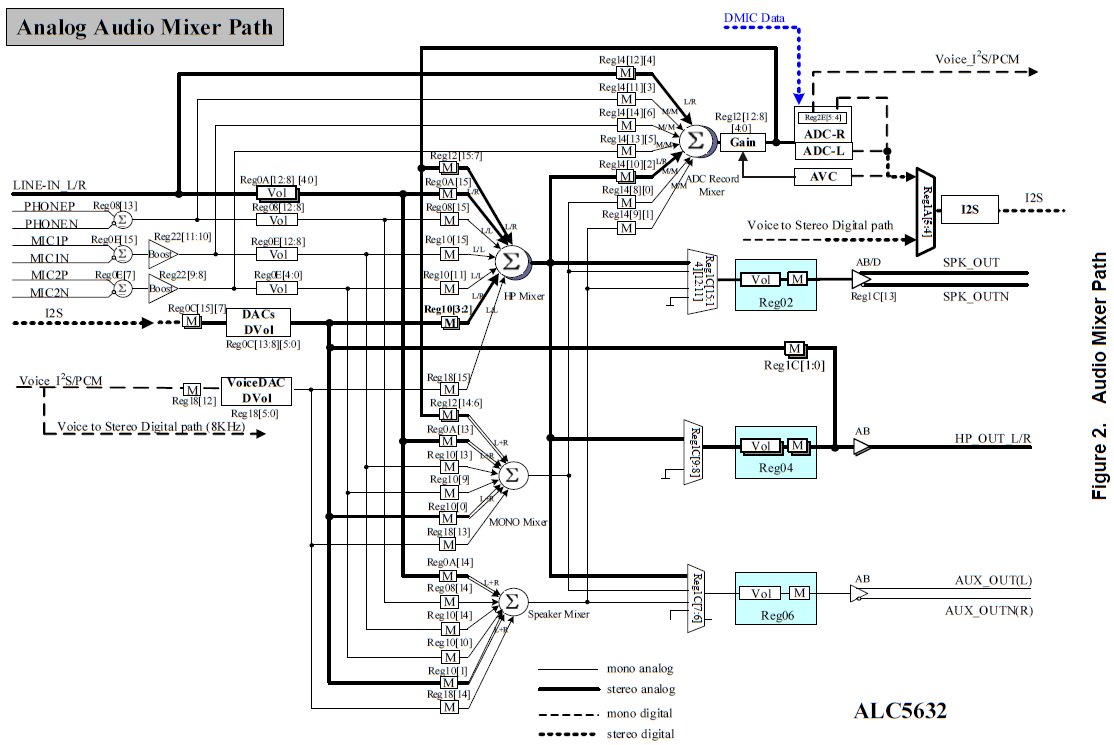
These netbooks utilize the ALC5632 audio codec along with a mixer IC, which features a number of knobs and switches. Most of these controls can be directly manipulated using alsamixer, GNOME Volume Control, and other applications that interface with...
The objective was to construct a moving coil (MC) sensitive preamplifier that is quiet, utilizes only vacuum tubes, and possesses a unique quality that invites listening. This preamp operates quietly, and when assembled correctly, it is free from hum....
.gif)
This circuit utilizes a single integrated circuit (IC) along with a minimal number of external components to display audio levels through ten LEDs. The input voltage range is from 12V to 20V, with a recommendation for 12V. The LM3915...
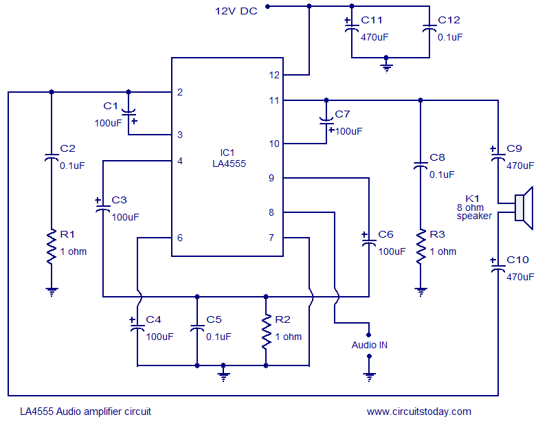
The LA4550 audio amplifier operates in a BTL (Bridge-Tied Load) configuration. This amplifier is capable of delivering 4W into an 8-ohm load when powered by a 12V power supply. The LA4550 is designed for audio amplification applications, particularly in situations...
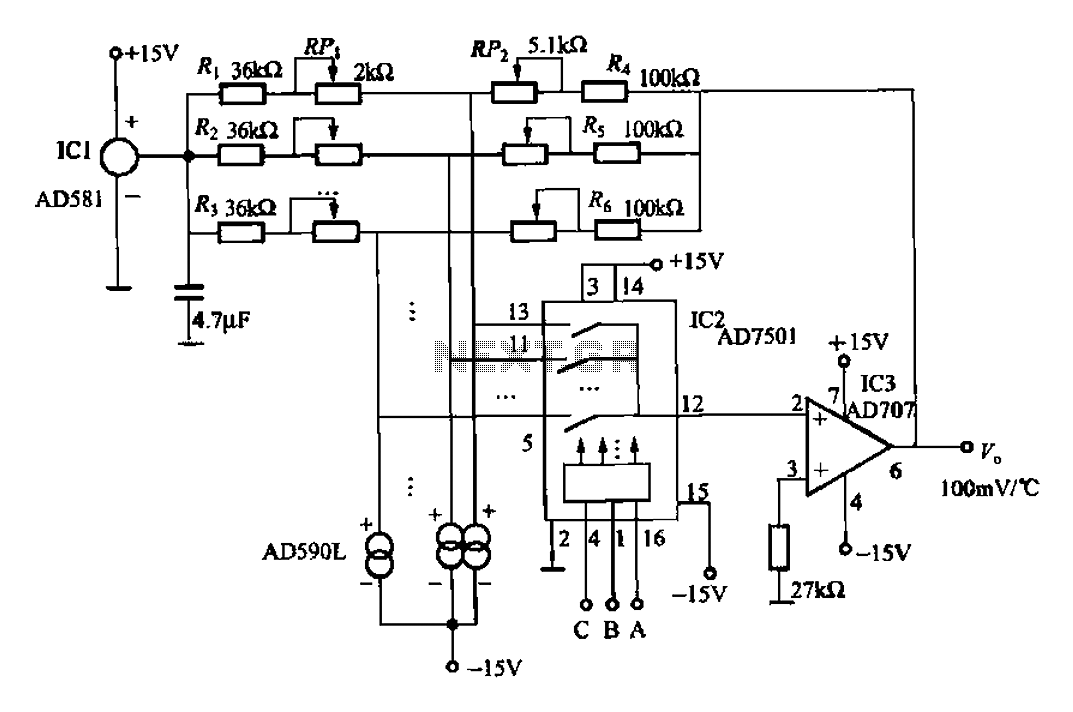
An 8-channel temperature detection circuit capable of monitoring eight different temperature sensors. The D581 serves as a 10.00V precision reference voltage source, providing a stable reference level for the detection circuit. Resistors RPi, RP2, and R4, along with the...
The TS2418 is a monolithic integrated circuit telephone tone ringer that utilizes a bridge diode. When paired with an appropriate transducer, it serves as a replacement for traditional electromechanical bells. This device is compatible with either a piezo transducer...