
Izzy Wizzy Audio

The circuit design of the MC sensitive preamplifier emphasizes the importance of minimizing noise and achieving high fidelity in audio reproduction. The single-ended design approach, while susceptible to power supply noise, is mitigated through the careful layout of the audio ground, ensuring that all components connect directly to a low impedance reference. This design choice enhances signal integrity and reduces the potential for unwanted noise modulation.
The use of a high-rated transformer ensures adequate power delivery while minimizing the risk of saturation, which can affect audio quality. The choice of MV diode rectifiers, complemented by small inductors, addresses potential ringing issues, resulting in a smoother audio signal. The implementation of a choke input power supply further contributes to the overall sound quality by providing a more natural and dynamic audio output.
The design's reliance on a mono power supply configuration is a strategic decision aimed at achieving a coherent sound stage. By eliminating the complications associated with dual mono supplies, the circuit benefits from a unified ground reference, enhancing the clarity and spatial representation of the audio signal.
In summary, the MC sensitive preamp is engineered to prioritize sound quality and detail retrieval, achieved through a meticulous selection of components and a thoughtful circuit layout. The careful consideration of power supply design, grounding techniques, and component choices culminates in a preamplifier that delivers an engaging listening experience while remaining faithful to the original musical performance.The aim was to build a MC sensitive preamp that was quiet, used only tubes and had a certain something that made you want to listen. This thing is quiet and if built properly, hum free. I have to put my head very near the speaker to hear a slight trace of hum or hiss at loud listening levels.
The main design aim other than to make it sound good wa s to give the circuit a solid reference. Single ended circuits "pass on" virtually every bit of power supply noise. This noise may not be audible in its own right but it will modulate the signal passing through the gain stage. Part of providing a solid reference is getting and maintaining an unambiguous and relatively low impedance audio ground.
The audio ground is a single foil conductor about 20mm long. All the audio components are connected to it using their leads only - no extra wiring is used. The circuit is shown almost exactly as it is wired. Another design aim was to trust the components to do their job. "A sound" was not the aim but it was designed to allow as much as possible to be heard detail wise but also to maximise the connection to the musician(s) and allow the musical message through. This is very hard to explain and I was surprised how delicate this balance was. The simpler it got, the better it became up to a point. The more iron/coils I threw at it, the better in these terms it became especially rhythmically. Any additions to "help" the circuit such as active/CCS loads and regulators etc got in the way. As the PSU got better, the less these things were needed. If the PSU is average, then these circuit "tricks" can be used to advantage as they isolate the audio circuit from bad power supply artifacts.
After using dual mono supplies for years, it occured to me that it is impossible to provide a common clean ground reference using this approach hence the main outboard supply is mono in design. The sound seems more coherent this way. The transformer is 4x overated for the duty - whether this is needed for choke input is debateable. Rectification is by MV diode rectifiers - they were not compared to other types but are effortless in sound and look brilliant.
The small inductors in their anodes suppress their tendency to ring a bit on start of conduction. The supply is choke input which provides a big easy sound - preferred to capacitor input. All transformers have earthed electrostatic screens. Modelling using the superb Duncan`s Amp PSU designer produced the design results. The DC voltage as modelled was 298V; 301V in reality using the 83 rectifier and design values for the chokes. Note the transformer is 340-0-340 @ 200mA so measured about 370V with the load of the preamp circuit.
Ripple at the PSU output modelled at 0. 5mV. After the RCLC stage, ripple is approx 20nV and will be much less for the first stage. I can`t see any regulator achieving these figures and so contributes to the quietness and lack of program induced noise that indicates a poor power supply. The heater supply is similar in topology to the HT and contains the only solid state device, a schottky dual diode.
The 0. 1H 3A chokes decimate ripple and therefore even in an MC sensitive preamp, no regulator is required for low noise/hum. The common mode choke helps to attenuate hash and rubbish that has come in on the mains or transients caused by the diodes switching.
The secondary also benefits from a resistor which I guess damps oscillations caused by diode switching. A similar arrangement on the HT produced no discernable benefit. A key component in this design is the TX103 Stevens and Billington MC step up transformer. A superb device; the closest thing to a wire with gain I`ve heard and that is exactly what I replaced when I tried it - a piece of wire.
I`d concede it is the superiour matching and energy transfer that this allows to be crucial. All previous transformers I`ve heard have obscured something or other so straight into a high 🔗 External reference
Related Circuits
The circuit described is a metal detector. The operation of the circuit is based on the superheterodyne principle, which is commonly used in superheterodyne receivers. The circuit utilizes two RF oscillators, both fixed at a frequency of 5.5 MHz....

When switches SW1, SW2, or SW3 are open, the input sensitivity is optimized for high-output devices such as CD players, tuners, tape recorders, iPods, miniDisc players, and computer audio outputs. The 750 Ohm value for resistors R3, R13, and...
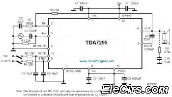
The IC TDA7295 is a monolithic integrated circuit designed for use as an audio class AB amplifier in high-fidelity applications, including home theaters and high-end televisions. The TDA7295 is a versatile audio amplifier that delivers high-quality sound reproduction, making it...
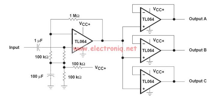
This audio distribution electronic project circuit diagram is designed using the TL064 or TL06 operational amplifiers and some other common electronic parts. The audio distribution circuit utilizes TL064 or TL06 operational amplifiers, which are quad op-amps known for their low...
A small audio test generator is highly effective for quickly tracing signals through audio equipment. Its primary function emphasizes speed over precision. Typically, a single sine-wave signal of approximately 1 kHz suffices, and distortion levels are not critically important....
This is a diagram of a car audio active loudspeaker utilizing the LF353 operational amplifier from National Semiconductor. For optimal performance, the NE5532 is recommended to split the audio signal into three frequency bands using an active filter. The...