
Sub-Harmonic Bass Converter for Electric Guitars
The system functions by connecting two series split-circuit circuits that receive the input signal and mix their output with the original signal. However, several factors must be considered for proper operation. Firstly, the input signal needs to be processed into square pulses to ensure reliable operation of the digital dividing circuits. Secondly, the output signals from the splitting circuits are square waves, which inherently contain strong harmonics that can distort the intended bass sound. Thirdly, the generated signals maintain the original amplitude and shape, leading to a loss of sound quality as the note fades. Finally, the divisor may produce unwanted pulses when the input signal drops below a certain threshold, resulting in audible clicks and buzzes that overshadow the guitar's natural decay.
To address these issues, the circuit is designed to avoid such imperfections, as illustrated in the accompanying block diagram.
The input signal is directed to a mixer and amplifier, where it is amplified and fed into a trigger circuit. If the input signal exceeds a specified threshold, the trigger circuit outputs a high logic level. The trigger circuit introduces a significant lag, ensuring that the input signal required to switch the output to logic '1' is higher than that needed to return to logic '0'. This design mitigates problems caused by electrical noise or irregular waveforms from the guitar. The output of the trigger circuit abruptly cuts off the output signal from the dividers, although occasional random output pulses may still occur when the input signal diminishes.
The trigger circuit controls two dividers, producing signals that are one and two octaves lower than the original input. The resulting sub-multiplied signals are mixed at user-defined levels before passing through an active low-pass filter. The cut-off frequency of this filter requires careful selection; a higher cut-off frequency results in unnatural harmonic outputs, while a lower frequency may degrade the quality of high notes produced by the guitar. Originally set at 250 Hz, this frequency can be adjusted by changing the values of three resistors.
The filtered signal is then sent to a voltage-controlled amplifier (VCA), which adjusts the amplification based on the control voltage derived from the amplitude of the guitar signal. This VCA provides a natural shape to the sub-multiplied frequencies, allowing for a smooth transition in sound. Although the envelope of the sub-multiplied frequencies does not perfectly match the input signal, this difference can enhance the perception of the bass as a distinct instrument. The VCA has a high output impedance, connecting to the first mixer through an isolation amplifier.
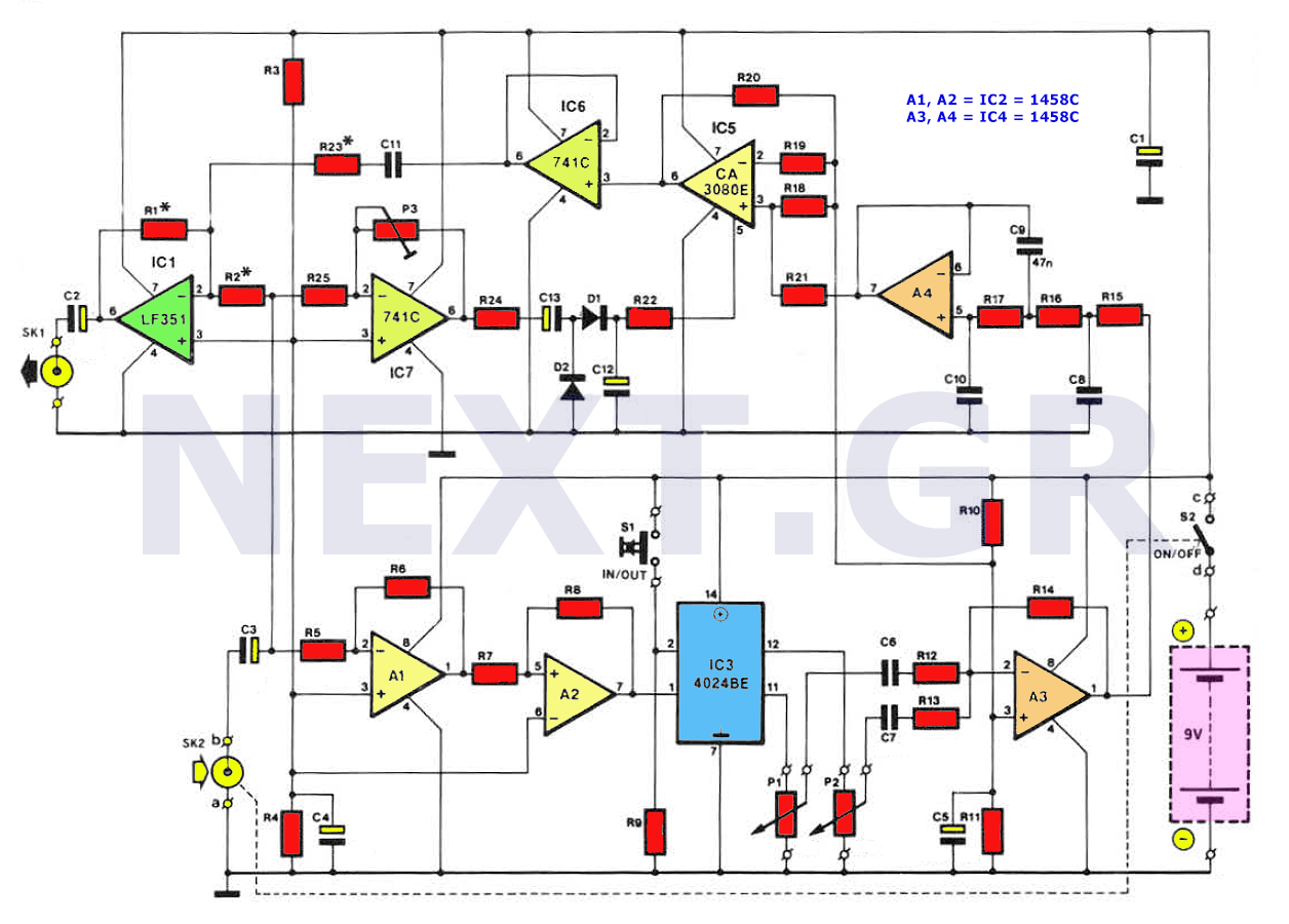
The modulating circuit of the envelope is based on an input mixer (IC1), which is a standard amplifier utilizing the LF351 boost amplifier, powered by a simple 9V supply. A voltage divider formed by resistors R3 and R4 provides bias voltage to the non-inverting inputs of IC1 and A1. The input amplifier comprises A1 and associated components, functioning as a simple inverting amplifier with a gain of approximately 40 dB, determined by the resistor values R5 and R6. The circuit's high input impedance is maintained through various resistors.
The splitting function is achieved using a CMOS digital divider (IC3), specifically the 4024BE, utilizing only the first two stages. The reset input of IC3 is grounded via R9, ensuring proper operation of the splitter. A foot switch (S1) allows for easy activation or deactivation of the sound effect. Potentiometers P1 and P2 control the intensity of the two generated signals, which are mixed in another additive mixer (A3) with a low amplification factor to prevent signal clipping.
The low-pass filter around A4 operates with an 18 dB/octave gradient and a cut-off frequency of approximately 250 Hz, adjustable by changing resistor values. The VCA (IC5, CA3080) is designed to amplify current rather than voltage, with the output current controlled by differential input currents. The circuit also employs various resistors for biasing and load resistance to convert current amplification to voltage amplification.
The generator is powered by a 9V battery, consuming approximately 6 mA. The design includes a switch (S2) that activates the power only when a guitar is connected. The output is connected to an amplifier through a shielded cable, and adjustments can be made to the potentiometers for optimal sound quality.
The construction involves mounting components on a PCB, with careful attention to the orientation of certain ICs and the handling of sensitive components like diodes. The enclosure is designed for durability and noise shielding, with appropriate insulation to prevent short circuits.
In summary, the sub-harmonic bass generator is a sophisticated circuit that effectively generates bass-like sounds from a guitar input while addressing potential issues related to signal processing and output quality. The careful design and component selection ensure a high-quality audio experience, making it suitable for musicians seeking to expand their tonal palette.The sub-harmonic bass generator is a sound producing unit for guitars. The sound it produces looks very much like that of the bass guitar. The octave generator is sometimes quite unusual since it does not produce any of the usual ways of coloring the sound, such as filtering or distortion. Instead, a frequency division system produces outputs with half the input frequency and its fourth. That is, it produces frequencies of one and two octaves lower than the input frequency which are then mixed with the input signal.
For this device to work properly, the circuit must be somewhat more complex than one might expect initially for reasons that we will analyze below. However, although the design of the circuit is relatively simple, the sound output it produces is excellent.
The mechanical construction of the unit is of a pedal type, allowing you to activate or interrupt the foot effect. The two signals produced by the circuit have separate amplification control each, so they can be mixed with the original signal at any desired level.
Function of the system
All that is needed is two series connected split-circuit circuits for two, which are fed with the input signal and their output signals are mixed with the original input signal. In practice, this will not work properly for several reasons.
First of all, the input signal must be processed to take the form of square pulses, which is necessary for the digital dividing circuits to work reliably.
Second, the output signals of the splitting circuits will be square and will therefore have many strong harmonics, so the sound that is produced will not look like anything in the bass sound.
Thirdly, the signals generated by the division do not have the originally large width that suffers smooth damping but are presented with the appearance of the original signal, continue with the same amplitude and as the note fades as soon as it reaches the point it can not excite now the circuit is lost.
This creates the fourth and final problem.
which is that the divisor does not cut off "Pure" and is almost certain to produce unwanted pulses when the input signal drops below the level that can lead it. This will create strong 'CLICK' and buzz sounds that will sound much stronger than the guitar's note that turns off slowly.
This circuit is designed so that it does not have any of these imperfections and the way it works is explained in the following block diagram.

Operating circuit
The input signal feeds a mixer and amplifier.
The amplified signal is driven into a trigger circuit. If the input signal has a width greater than the specified threshold level, the output of the trigger circuit is led to a high logic level
The trigger circuit introduces a large lag, which means that the input signal level that switches the output of the trigger circuit to logic '1' is much higher than that allowing it to return to logic '0'. This lag helps to eliminate the problems caused by the accidental switching of the output, generated by electrical noises that may exist in the input signal or by the slightly irregular waveform of the signal given by the guitar.
The following figure explains how the lag provides us with this result,

which we need especially when the signal produced by the guitar is almost zero. The result of the triggering circuit is the totally abrupt cut off of the output signal of the dividers, which however can not always ensure that sometimes there will be few random output pulses at the moment when the input signal goes out, it drops to a level that is incompetent to drive the circuit.
The trigger circuit drives two divisors for two.
which are connected one after the other, which produce the signals that are one and two octaves lower than the original input signal. The two sub-multiplied signals are mixed with the desired level for each and the composite signal is led to an active low pass filter.
To determine the cut-off frequency of this filter, we are compelled to make a compromise.
If we set a high cut frequency, it will give us a high-harmonic output and the final sound will sound abnormal, and if the frequency is too low, the result will be a serious downgrading of the divider's output frequencies when the guitar produces the highest notes of its scale. In the original, the 250 Hz frequency was selected, but you can, if you like, change it simply by changing the values of three resistors.
The filtered signal is driven to a voltage-controlled amplifier (VCA).
Its amplification is directly proportional to the control voltage which varies according to the amplitude of the signal produced by the guitar. So the voltage-controlled amplifier (VCA) gives a natural shape to the sub-multiplied frequency environments and to that of the guitar, which has sharp elevation and soft damping.
The control voltage is obtained by amplifying a part of the input signal which is then rectified to give us a constant voltage exactly proportional to the amplitude of the input signal.
In practice the envelope of the sub-multiplied frequencies is not exactly the same as the input signal, which is not so important and we consider it rather advantageous as the sub-multiplied signals sound a little different from the input signal. This helps to create the illusion that the "bass" comes out of a separate musical instrument.
The important acoustic effect of the encircling circuit is that sub-multiplied frequencies fade to levels that are not heard at the moment when the outputs of the dividers. Even if the outputs of these stages fail to cut completely, there is no problem, because the random pulses that will appear at the splitter's outputs will not be heard.
The VCA amplifier has a very high output impedance which is connected to the second input of the first mixer via an isolation amplifier.
Circuit description
The part of the modulating circuit of the envelope is shown in the figure below

Input Mixer IC1, is an ordinary amplifier based on the LF351 boost amplifier.
The entire unit is powered by a simple 9V supply which is better than a dual symmetric power supply. The resistors R3 and R4 isolated from C4 form a voltage divider connected in parallel to the feed lines, which gives us the bias voltage of the non-inverting inputs of IC1 and A1.
The input amplifier consists of the A1 and the elements connected thereto, being a simple inverting amplifier circuit with a voltage amplification of approximately 40 dB, which is determined by the ratio of resistors R5 and R6. The resistor R5 defines the input impedance of the amplifier around 100K, which together with the resistor R2 defining the input impedance of the mixer at 100K and the R25 defining the impedance modulus impedance of the envelope at 56K, give the whole the circuit has the appropriate high impedance of approximately 25K.
The power amplifier A2 is connected so as to function as a typical Schmitt-type trigger circuit with positive feedback and hysteresis provided by R8.
The splitting steps are present in IC3 which is a digital divisor of seven CMOS type 4024BE. Only the first two steps are used from this integrated circuit and the others are ignored. Of course, it was possible to use more IC3 outputs and drive them through voltage boost circuits in the mixer, but that would not give us any significant improvement since the output and the third tier is in the sub-acoustic area except when the highest notes on the scale are played on the guitar.
Terminal 2 is the IC3 resetting input and grounded via R9, allowing the splitting circuit to work properly.
However, whenever the foot switch S1 is pressed, the zero input is led to a high level, which cuts off the splitter and thus gives you a simple way to put or remove the sound effect. The potentiometers P1 and P2 control the intensity of the two signals and an octave below the base input frequency.
They are connected to another additive mixer, A3 having a voltage boost factor well below the unit for each input to the output. This low amplification is necessary because the signal of each input has a voltage level from peak to peak (Vpp) greater than that which is able to output at its output A3.
The low pass filter formed around A4 is a third class and quite common.
It has an 18dB / octave gradient and its cut-off frequency is around 250Hz. You can change this frequency easily by changing the resistance values R15 to R17. Frequency is inversely proportional to the resistance value. If you want to double it, for example, the value of the resistors must be reduced to half the value given in the drawing.
In the encirclement circuit the IC7 is a voltage amplifier whose amplification can be changed between zero (0dB) and about 25dB via the P3 for minimum and maximum resistance, respectively. This allows the circuit to operate in an extended input station area and it is necessary to set the P3 for proper voltage amplification.
The very low amplification will result in the circuit having an insufficient output signal level while the above normal amplification will tend to keep the output signal for a long time. The diodes D1 and D2 make the signal recalculate while C12 smooths the continuous voltage produced.
The attack time and the decay time of the circuit are very small, so that the circuitry of the envelope responds as directly as possible to the level changes of the input signal, but we have avoided making them too small because they would cause severe distortion.
The voltage-controlled amplifier (VCA), IC5 is a CA3080 CTA transducer. Although the Local Authorities have some common features with the common power amplifiers (including the differential inputs), there are several differences.
The most important of these is that a transducer (CTA) behaves primarily as a current amplifier and not as a voltage amplifier. For this reason the output current is controlled by the differential input current. There is also an input polarization of the amplifier (which in our case is the pin 5) and the amplification of the CTA is determined by the polarizing current supplying this input
In fact, the amplification is proportional to this polarization current.
In most cases, the operation of the circuit in a power amplifier rather than a voltage is much simpler. Fortunately, the transformation of the current boost function into a voltage amplification function is done by adding in series input resistors and load resistance at the output, which in the case of our circuit are respectively R21, R22 and R20.
Resistors R18 and R19 are input bias resistors.
The power transducer (CTA) has a very high output impedance and especially when operating with a low control current, for this reason the IC6 functions as a decoupling stage for the low output impedance. The output of the IC6 leads to the reversing input of the step mixing IC1.
The harmonics generator is powered by a 9V battery.
This power supply is quite economical because the circuit only draws about 6mA. The S2 switch is located inside the socket of the SC2 input socket. Thus, the device is powered only for the guitar input socket in the SK2 socket while the power is disconnected when it comes out of the socket. In fact, the SK2 socket has two switching contacts inside of which we ignore the contacts that are not needed.
Construction
All components other than the potentiometer, switches, plug connectors and battery are mounted on the board shown in the following figure.

Take care of IC3, because it is a MOS accessory, so be sure to place it on a 14-pin DIL base, even if all other accessories are stuck directly onto the board.
Of course take care of the IC3, to take all the necessary precautions.
The D1 and D2 passages are German and therefore sensitive. Their sensitivity is to heat and not to static loads. Make sure you do not warm them up more than is absolutely necessary when you stick them on the board to make correct weldings.
There is nothing more to trouble you in building than IC5 and IC6 have a different orientation than the other integrated.
At this stage, you have to place cable welding spikes on the board, where the various off-board components are to be connected in the future.
The box to be used is to be cast which, in addition to very good shielding against the electrical noise of the grid and other parasites, also has a great deal of resistance to mechanical stresses, which is necessary in such a construction with foot switches that will otherwise dissolve whenever you want to use it. In this construction the box is used upside down and its removable side is the base The switch S1 is placed on the upper side of the box, while the potentiometer and the connector sockets are placed side by side on one of the lateral sides that plays the role facade.
None of these cables need to be shielded.
so you prefer to use a common cable or tape-band pieces that they do for the case. When you finish the wiring, place the board in the box with four plate guides so that it is securely attached. Drivers need to be scraped carefully to securely fit inside the box.
The board is placed near the base of the box with the material side toward the base.
We recommend that you cover the inside of the base with a few sheets of self-adhesive insulating material or tape to avoid any accidental short-circuit and terminal contact with the inside of the box.
Regulation
As mentioned above, the generator starts to operate automatically as soon as the plug that attaches to the guitar with a shielded cable is inserted into the SK2 socket and is of a common type. Every time you stop using the unit, remove the plug from the SK2 socket to save the battery. The output from the SK1 socket is connected to the amplifier via a second shielded cable which at its end has a common type plug
By positioning the potentiometer P3 just in the middle of the stroke, the device must work well, while with P1 and P2 you can adjust the levels of the sub-harmonic signals.
After a few failed attempts you will be able to achieve the correct set point of P3. If you turn it over in the opposite direction from the clockwise direction, it will greatly weaken the sub-harmonic signals, even if you turn the P1 and P2 almost to the maximum of their travel.
If you turn P3 in the direction of the clock indicators more than necessary, the low-frequency (sub-harmonic) signals will be over-amplified and will be distorted while having a long duration. In any case, the best setting for P3 is that position you find turning clockwise, in which the signals of the sub-harmonics are not deformed and not abruptly cut off (ie, they quench gently and naturally).
However, its exact setting is unfortunately very critical.
The unit will work properly with most types of guitar magnet, although for those types that have a very low output level, it may be necessary to use a preamplifier to get really good audio results.
The best results of the bass sound effect are when you turn P3 to the minimum and P1 towards the end of the path so that only the signal of the second sub-harmonic (two octaves below the original signal). The signal of the first sub-harmonic (an octave below the original input signal) does not give any special feature of the bass sound but gives a much richer final audio effect and is used to make the effect better.
Components
Resistors:
R1, R2, R5, R23 = 100K
R3, R4, R9 = 4R7
R6 = 10M
R7, R20, R21 = 15K
R8, R14 = 47K
R10, R11 = 10K
R12, R13 = 220K
R15, R16, R17 = 39K
R18, R19 = 220
R22 = 22K
R24 = 3R3
R25 = 56K
P1, P2 = 47K potentiometers
P3 = 1M trimer
P4 - 220K potentiometer
Capacitors:
C1, C4 = 100μf / 10V
C2 = 10μf / 25V
C3, C12, C13 = 1μf / 63V
C5 = 470μf / 10V
C6 = 100n
C8 = 33n
C9 = 47n
C10 = 3n3
C11 = 330n
Semiconductors:
IC1 = LF351
IC2, IC4 = 1458C
IC3 = 4024BE (CMOS)
IC5 = CA3080E
IC6, IC7 = 741C
D1, D2 = OA91
Related Circuits

A replacement remote control system for an electric garage door was constructed after the original remote failed multiple times. Although the old remote could have been repaired, it was 35 years old and not particularly enjoyable to use. The...
The circuit below is a DC to DC converter using a standard 12 VAC center tapped power transformer wired as a blocking oscillator. The circuit is not very efficient but will produce a high voltage usable for low power...
The electric water heater temperature control circuit includes functions for water level indication, temperature regulation, anti-dry protection, and automatic leakage power protection, ensuring safety and reliability. The circuit consists of a power circuit, leakage protection circuit, temperature control circuit,...
This document provides information regarding the wiring of the Toyota Tercel 1996. Component: intake air temperature sensor. The intake air temperature (IAT) sensor in the 1996 Toyota Tercel plays a crucial role in the vehicle's engine management system. It is...
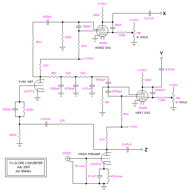
This project is a VGA-to-Scope converter that utilizes composite video signals instead of VGA signals to display on an oscilloscope. The design has been simplified by removing op-amp buffers and inverters. A simple 1 Megohm potentiometer is used to...
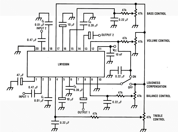
The LM1036 is a DC-controlled circuit designed for adjusting bass, treble, balance, and volume in stereo applications, particularly in car radios, televisions, and audio systems. An additional control input enables the implementation of loudness enhancement. Four control inputs facilitate...